

Project Solutions
Simple Audio Peak Detector
Published:2011/8/12 1:07:00 Author:Amy From:SeekIC
Flemming Jensen
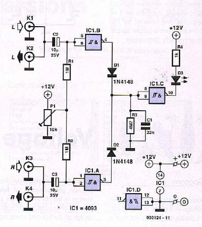
This audio peak detector allows a pair of stereo channels to be monitored on a single LED.
Identical circuitry is used in the left and right channels. Use is made of the switching levels of Schmitt trigger NAND gates inside the familiar 4093 IC. The threshold level for gate IC1 .A (IC1 .B) is set with the aid of preset PI, which supplies a high-impedance bias level via R2 (Rl). When, owing to the instantaneous level of the audio signal superimposed on the bias voltage by C3 (C2), the dc level at pins 1 and 2 (5 and 6) of the Schmitt trigger gate drops below a certain level, the output of IC1.A (IC1.B) will go High. This level is copied to the input of IC1 .C via D2 (Dl) and due to the inverting action of IC1 .C, LED D3 will light. Network R3-C1 provides some delay to enable very short audio peaks to be reliably indicated.
Initially turn the wiper of PI to the +12 V extreme — LED D3 should remain out. Then apply ’line’ level audio to Kl and K3, preferably music with lots of peaks (for example, drum ’n bass). Carefully adjust PI until the peaks in the music are indicated by D3.
The circuit has double RCA connectors for the left and right channels to obviate the use of those rare and expensive audio splitter [T] cables.
Reprinted Url Of This Article: http://www.seekic.com/blog/project_solutions/2011/08/12/Simple_Audio_Peak_Detector.html
Print this Page | Comments | Reading(1283)
Article Categories
New published articles
· Imagination works with TSMC to develop FinFET process
Author:Ecco Reading(49277)
· XMOS pushes event-driven MCUs with lower price
Author:Ecco Reading(4246)
· Intel brings upgraded 32-nm SoC for smartphones
Author:Ecco Reading(3968)
· Micron pushes TLC 128-Gbit NAND flash
Author:Ecco Reading(4707)
· Intel will stop supplying desktop motherboards
Author:Ecco Reading(6046)
· Processor market was expected to regain strength in 2013
Author:Ecco Reading(4043)
· It was reported that TSMC sales fall steeply
Author:Ecco Reading(3714)
· Cisco, NXP work with auto wireless startup
Author:Ecco Reading(4377)
· Micron was impacted by manufacturing glitch
Author:Ecco Reading(4731)
· China can make 22-nm transistor by themselves
Author:Ecco Reading(4593)
· Chip market rebound is coming, according to survey
Author:Ecco Reading(4471)
· Sony, Toshiba will spend more on chips, iSuppli reports
Author:Ecco Reading(4032)
· Qualcomm becomes the 13th company to join NFC Forum board
Author:Ecco Reading(6893)
· TSMC increases building work for FinFET fab
Author:Ecco Reading(4556)
· TI plans to cut 1,700 jobs in OMAP shift
Author:Ecco Reading(5434)