

Project Solutions
EL156 AUDIO POWER AMPLIFIER Return of a legend (1)
Published:2011/8/15 22:24:00 Author:Phyllis From:SeekIC
By Gerhard Haas
Thanks to its robustness, the legendary EL156 audio power pentode has found its way into many professional amplifier units. Its attraction derives not just from its appealing shape, but also from its impressive audio characteristics. We therefore bring you this classical circuit, updated using high-quality modern components.
The EL156 was manufactured in the legendary Telefunken valve factory in Ulm, near the river Danube in Germany. The EL 156 made amplifiers with an output power of up to 130 W possible, using just two valves in the output stage and one driver valve. Genuine EL156s are no longer available new at realistic prices, and hardly any are available second-hand. The original devices used a metal valve base which is still available, but a new design using original valves and metal valve bases would anyway be impractical, given the lack of availability at reasonable prices.
Made in China
Fortunately this valve is still being produced in China, using the original Telefunken machines. A normal octal base is now used, with pinout the same as that of the EL84, 6L6, KT88 and similar valves. The devices are still not exactly cheap, but the price is not too unreasonable and the valves are generally supplied with bases included. Comparison with original Telefunken valves shows that the devices are a successful mechanical and electrical copy and are suitable for use in a hi-fi amplifier.
Before we proceed to describe the design, we should first look at a few special features of these valves. In the text box we compare the basic specifications of the EL156 with those of the well-known and widely-used EL34. This information will to a large extent determine the design of the amplifier. In order to obtain sufficient output power, the anode voltage must be at least twice as high as the screen grid voltage. The driver circuit must be designed to cope comfortably with the comparatively low-impedance load presented by the grid leak resistors. The popular ECC83 (12AX7) is ruled out, since it operates at only around 1 mA. The ECC82 (12AU7) audio double triode can be operated with an anode current of 10 mA, and so would appear to be suitable; however, its open-loop gain is only 17, which is not enough to give adequate sensitivity, even before allowing any margin for negative feedback. The ECC81 (I2AT7). however, which has an open-loop gain of 60 and which can be operated with anode currents of up to 10 mA, can be used to build a suitably low-impedance circuit.
Two EL 156s can be used to produce an output power of 130 W with only 6 % distortion. To improve reliability and increase the life of the valves, however, we have limited the maximum power. A genuine hi-fi output at 100 W with low distortion is better than 130 W at 6 %, especially when there is a large component at the unpleasant-sounding third harmonic. 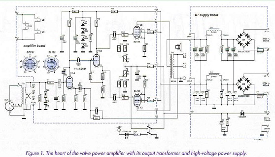
The whole circuit is built on four printed circuit boards, forming a monoblock. Figure 1 shows the power supply and the amplifier together. The power supply capacitors are cascaded to filter the high anode voltage in order to obtain the required voltage stability. To supply the relatively high currents required by the screen grids of the EL156s two separate high voltage supplies are produced using bridge rectifiers from two isolated transformer windings (’hi’ and ’lo’). Immediately after the rectifiers these supplies are connected in series and individually filtered. Choke Drl, with a value of 2.3 H, is rated for a current of 0.3 A and filters the anode supply, while Dr2, with a value of 4 H and rated for 0.18 A, filters the screen grid voltage. The driver valve is also powered from the screen grid supply. The screen grid voltage must be well filtered since any hum present on it will be amplified through to the output: the screen grid has some control effect. The values suggested give good filtering and hence low hum. Radial IOO/JF/500 V electrolytic capacitors are recommended to make the power supply compact; a working voltage of 500 V ensures adequate margin to give reliable operation even in the event of mains overvoltage. Note the discharge resistors in parallel with the electrolytics. The negative grid bias voltage is provided by a diode and electrolytic capacitor: this voltage is further filtered on the amplifier board.
Reprinted Url Of This Article: http://www.seekic.com/blog/project_solutions/2011/08/15/EL156_AUDIO_POWER_AMPLIFIER_Return_of_a_legend__(1).html
Print this Page | Comments | Reading(5506)
Article Categories
New published articles
· Imagination works with TSMC to develop FinFET process
Author:Ecco Reading(30027)
· XMOS pushes event-driven MCUs with lower price
Author:Ecco Reading(3456)
· Intel brings upgraded 32-nm SoC for smartphones
Author:Ecco Reading(3178)
· Micron pushes TLC 128-Gbit NAND flash
Author:Ecco Reading(3649)
· Intel will stop supplying desktop motherboards
Author:Ecco Reading(5225)
· Processor market was expected to regain strength in 2013
Author:Ecco Reading(3242)
· It was reported that TSMC sales fall steeply
Author:Ecco Reading(3385)
· Cisco, NXP work with auto wireless startup
Author:Ecco Reading(3526)
· Micron was impacted by manufacturing glitch
Author:Ecco Reading(3932)
· China can make 22-nm transistor by themselves
Author:Ecco Reading(3701)
· Chip market rebound is coming, according to survey
Author:Ecco Reading(3673)
· Sony, Toshiba will spend more on chips, iSuppli reports
Author:Ecco Reading(3708)
· Qualcomm becomes the 13th company to join NFC Forum board
Author:Ecco Reading(6023)
· TSMC increases building work for FinFET fab
Author:Ecco Reading(3686)
· TI plans to cut 1,700 jobs in OMAP shift
Author:Ecco Reading(4473)