

Project Solutions
I²C-homebus: Switch power outlets with your PC 1
Published:2011/8/16 3:20:00 Author:Amy From:SeekIC
Paul Goossens
This unit, in combination with the USB/I2C interface described elsewhere in this issue, may be used to switch four mains-powered devices on and off via the PC. Eight of these modules may be connected to a single interface, allowing up to 32 loads to be controlled. The system is ideal for a small home bus!
Triggered by other articles on home automation in this issue, you may feel like investigating the possibilities of automating, or at least remote controlling, a couple of electrical devices in and around your home. If you do not want to rush off to the high street stores to buy a box full of ready-made modules working on a more or less familiar protocol, then home construction of a small system is a perfectly viable alternative.
An I2C system can be used without problems for a small home bus comprising a couple of features for control and switching. Provided extra bus drivers are applied, distances of the order of tens of metres are easily covered. The connecting cable between the modules is reasonably simple as we employ 6-wire UTP cabling with RJll plugs. Also, there is a wide choice of ICs with I2C compatibility, serving an impressive number of applications.
At the PC side we already have a suitable circuit in the form of our USB/I2C interface. Thanks to its design, this interface is capable of covering large distances and so forms the perfect starting point for a simple I2C-based Home Bus. At the ’device’ side there are a great many possibilities when it comes to creating an I2C connection. In this article we describe a circuit that allows four mains-powered devices to be switched (TV, lighting, coffee machine, etc.).
Several modules may be connected to the bus, so quite a lot of electrical equipment in and around the home may be ’bused’ in this way.
Keep it simple
As you can see in the circuit diagram in Figure I, the active part of the circuit consists of a remote 8-bit I/O expander type PCF8574 and an I2C bus extender type P82B715PN. 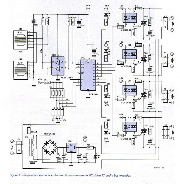
The PCF8574 in position IC3 contains an 8-bit bidirectional port and an I2C bus interface. The eight open-drain outputs can ’source’ sufficient current to drive LEDs directly. Thanks to internal latches, the IC remembers the most recent configuration. Four output pins control the four status LEDs in the circuit; the other four connections each serving a mains output. Actually, the LEDs and triacs are controlled separately via the bus, but the software written for the system will automatically ensure each LED will always indicate the status of the associated mains connection (i.e., triac).
Three pins (wired to DIL switch SI) allow one of up to eight module addresses to be set; meaning that up to eight of these circuits may be connected to a single bus — and addressed individually. It should be noted that the -A version of the PCF8574 has a different slave address range. If you use the PCF8574A in another eight modules, up to 16 modules may be connected to the bus. The bus extender IC, IC1, acts as a ’booster’, increasing the currents through the I2C bus and so making it less susceptible to external interference. If, as in our example, UTP cable is used, then a distance of about 200 metres may be covered between PC interface and module — more than enough to ’wire’ your average home we’d say.
Note that the extender IC has to be applied in all modules connected to the bus if it is also present on the USB/I2C interface board (or similar modules of your own design).
The connections with the I2C bus are routed via two RJ11 connectors on the board.
The mains-powered loads are switched on and off using a combination of an optoisolator and a triac. In this way we have a good electrical isolation between the mains on the one hand and the circuit and the Home Bus, on the other. The MOC3043 is an optoisolator with an internal diac and zero-crossing detector, which make it ideal for driving a triac.
The triacs used are the common-or-garden type TIC206D. They require a so-called snubber network to protect the device against voltage surges across the anodes. In this case, we’ve added a series network of a 39-_ resistor and a 10-nF capacitor for each triac. If you want to use so-called snubberless triacs, then resistors R15/R18/R21/R24 and capacitors C8/C9/C10/C11 may be omitted.
The low-voltage logic circuitry is powered from the mains using a transformer, a bridge rectifier, a reservoir capacitor and a 7805 voltage regulator. This power supply affords electrical isolation between the circuit and the mains network.
Reprinted Url Of This Article: http://www.seekic.com/blog/project_solutions/2011/08/16/Isup2;C_homebus__Switch_power_outlets_with_your_PC_1.html
Print this Page | Comments | Reading(3471)
Article Categories
New published articles
· Imagination works with TSMC to develop FinFET process
Author:Ecco Reading(30163)
· XMOS pushes event-driven MCUs with lower price
Author:Ecco Reading(3460)
· Intel brings upgraded 32-nm SoC for smartphones
Author:Ecco Reading(3180)
· Micron pushes TLC 128-Gbit NAND flash
Author:Ecco Reading(3660)
· Intel will stop supplying desktop motherboards
Author:Ecco Reading(5230)
· Processor market was expected to regain strength in 2013
Author:Ecco Reading(3247)
· It was reported that TSMC sales fall steeply
Author:Ecco Reading(3389)
· Cisco, NXP work with auto wireless startup
Author:Ecco Reading(3529)
· Micron was impacted by manufacturing glitch
Author:Ecco Reading(3934)
· China can make 22-nm transistor by themselves
Author:Ecco Reading(3706)
· Chip market rebound is coming, according to survey
Author:Ecco Reading(3676)
· Sony, Toshiba will spend more on chips, iSuppli reports
Author:Ecco Reading(3713)
· Qualcomm becomes the 13th company to join NFC Forum board
Author:Ecco Reading(6027)
· TSMC increases building work for FinFET fab
Author:Ecco Reading(3691)
· TI plans to cut 1,700 jobs in OMAP shift
Author:Ecco Reading(4477)