

Project Solutions
Delphi for electronic engineers: Part1-the first steps (4)
Published:2011/8/17 1:13:00 Author:Li xiao na From:SeekIC
Detlef Overbeek & Anton Vogelaar
The third program -an alarm system
This program provides protection against burglary and fire in a dwelling. The protected dwelling is divided into four zones. If there is an alarm condition in one or more zones this should be indicated both visually and aurally.
The alarm system is implemented as follows. Each zone contains a number of sensors with normally closed contacts, connected in series. In this way a sensor circuit is always closed until an alarm condition occurs in a sensor or the cable is cut.
A number of suitable sensors are shown in Figure 5. Since this system makes use of closed circuits, monitoring the alarm installation comes down to detecting whether or not the four sensor loops have breaks in them. The RS232 port in a PC has four inputs that can be used for this. 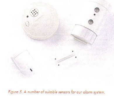
Should your PC not have a spare RS232 port, or wasn’t provided with one, you can use a USB/RS232 converter. (An RS232 port has a 9-way male connector on a PC).
The connection diagram is shown in Figure 6. Pin 4 is used to provide a voltage for the switches. The inputs on pins 1, 6, 8 and 9 will normally see this voltage or 0 V in an alarm condition. 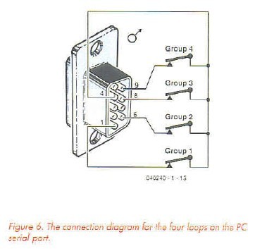
The program
1. Start a new project by choosing File/New/Applica-Hon from the menu.
2. Save the new project and give it a name via File/Save All or hold down the keys Shift+Ctrl+S simultaneously.
3. Put four rectangular Shapes from the Additional tab on the Form and set their properties: Shape = stRoundRect and Brush/Color = cIRed.
4. Put a Label from the Standard tab into each of the Shapes and set their properties: Caption = Group 1, Group 2, Group 3 and Group 4, Transparent = True and in the Font-property: Font = Arial, Font style = Bold and Size = 20.
5. Add a Timer from the System tab to the Form so that the state of the alarm sensors can be checked periodically. The Form should now look similar to Figure 7. 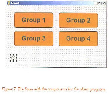
6. Before the state of the RS232 inputs can be read, the program has to open the communications port. This is done when the programs starts. When the program finishes the port is closed again, making it available for use by other programs. The OnCreate and OnDestroy events are used for this when opening and closing a Form respectively. If you double-click on the boxes to the right of these events in the Object Inspector for Form l, Delphi will add the code for these events in the Code Editor. You should now add our application code between the Begin and End lines (Listing 1). This code has references to the as yet undefined variable HComm and the constant PName.
HComm is a handle/number that refers to the communications port used. The value for this handle is returned by the operating system (Windows) via the function CreateFile. If the value of HComm is <= 0, the communications port could not be opened.
Since a PC may have more than one communications port, the constant PName has been added to the proqram. This contains the name of the communications port we want to use. In other words, if we want to use Com5 the value of PName should be ’Com5’. The variable HComm and the constant PName are defined in the header (Listing 2).
7. In the OnTimer event of the timer, which is called once per second by default, the status inputs are read and the corresponding indicators/Shapes will be set to green (teal) or red, depending on the alarm condition.
The function GetCommModemSiatus asks Windows for the state of the inputs of the communications port which is referred to by the value in HComm. The returned value is stored in the variable MdmSts, which is of a Cardinal type (o 32-bit number). The four inputs take up one bit each in MdmSts. By ANDing this with a mask (see listing 3, the masks ore MS_DSR_ON etc.) and testing if the result is ’0’, we know whether the bit is set or not (Listing 3). The result determines whether the Shape takes on a green or red color.
The SoundAlarm procedure is still commented out, but we’ll make use of this later.
Note that occasionally you may have to reset the PC in order to get the RS232 port to work properly.
8. The program can be enhanced with a sound output to draw the attention of the operator. We will use the PC loudspeakers for this. We have included an option to turn off the sound until the alarm condition has passed.
Put a CheckBox from the Standard tab on to the Form. Change the Caption property io ’Sound OP’.
Define a new procedure in the header, between the words Private and Public: Procedure SoundAlarm;
Remove the comment symbols before SoundAlarm in the OnTimer event
Write the procedure for SoundAlarm. The completed program should now look like Listing 4.
In this first installment we’ve managed to get through three examples and we may have covered some concepts rather quickly. But we’ve assumed from the start that those of you who are interested will want to broaden your knowledge of Delphi programming. You’ll soon find that programming can be both fun and instructive.
Reprinted Url Of This Article: http://www.seekic.com/blog/project_solutions/2011/08/17/Delphi_for_electronic_engineers__Part1_the_first_steps_(4).html
Print this Page | Comments | Reading(741)
Article Categories
New published articles
· Imagination works with TSMC to develop FinFET process
Author:Ecco Reading(30184)
· XMOS pushes event-driven MCUs with lower price
Author:Ecco Reading(3461)
· Intel brings upgraded 32-nm SoC for smartphones
Author:Ecco Reading(3181)
· Micron pushes TLC 128-Gbit NAND flash
Author:Ecco Reading(3661)
· Intel will stop supplying desktop motherboards
Author:Ecco Reading(5231)
· Processor market was expected to regain strength in 2013
Author:Ecco Reading(3248)
· It was reported that TSMC sales fall steeply
Author:Ecco Reading(3390)
· Cisco, NXP work with auto wireless startup
Author:Ecco Reading(3530)
· Micron was impacted by manufacturing glitch
Author:Ecco Reading(3935)
· China can make 22-nm transistor by themselves
Author:Ecco Reading(3707)
· Chip market rebound is coming, according to survey
Author:Ecco Reading(3677)
· Sony, Toshiba will spend more on chips, iSuppli reports
Author:Ecco Reading(3714)
· Qualcomm becomes the 13th company to join NFC Forum board
Author:Ecco Reading(6028)
· TSMC increases building work for FinFET fab
Author:Ecco Reading(3692)
· TI plans to cut 1,700 jobs in OMAP shift
Author:Ecco Reading(4478)