

Project Solutions
Intelligent Clap Switch: manual remote control with extras (1)
Published:2011/8/17 2:15:00 Author:Li xiao na From:SeekIC
Jorg Prim
A clap switch circuit is a classic beginner’s project. Equipment can be switched on and off by just clapping your hands. Add a tiny microcontroller and you can easily build-in some more useful futures.
The microcontroller in this circuit makes it a simple job to add some useful features that are not seen on other clap switch designs:
- Changeover relay contacts enable the unit to be wiled in conjunction with a manual changeover switch so that manual override of the switched equipment is always possible.
- The unit is only responsive to a specific sequence of sounds i.e., two claps within a defined time window.
- A safety feature masks the input for a given time window if misuse (repeated commands) is
detected (useful if children have discovered how it works).
The safety feature and two-clap sequence detector can be built using TTL or CMOS flip-flops but by using a single microcontroller the circuit can-be greatly simplified. A mains power supply is included so no additional power source is required.
A compact Controller
The Microchip flash PIC12F629 microcontroller is a neat device; the small 8-pin package contains a complete microcontroller including clock generator, reset circuitry, Flash ROM. RAM and EEPROM. Two of the eight pins are used for the supply connections while the remaining six are general-purpose I/O pins. A few of these pins have special function like the comparator inputs. The sound sensitivity of the circuit can be adjusted by programming the comparator threshold level in software. The circuit diagram in Figure 1 shows that besides the microcontroller there are very few other components. The two-pin electret microphone produces an electrical signal in response to sound pressure waves. Transistor T1 amplifies the signal and preset PI allows some adjustment of the circuit sensitivity by altering the bias voltage of T1. 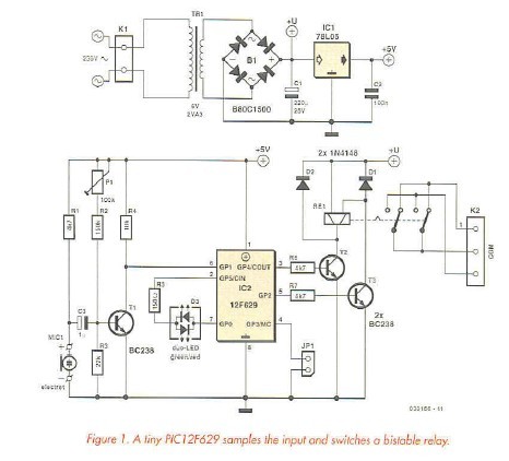
Two of the PIC output pins are used to drive a bistable relay via transistors T2 and T3. This type of relay has two energizing coils. A short electrical pulse on one of the coils is enough to switch the relay in one direction while a pulse to the other coil will cause the relay to switch back, This type of relay has two main advantages: the relay is latching in both open and close direction so a short pulse is all that is necessary to switch it. Secondly the latching feature ensures that the relay retains its switched state even during a power failure. Changeover relay contacts enable the unit to be wired together with a changeover type manual switch, allowing the equipment to be switched manually if for any reason the clap switch is switched off.
Pins 2 and 7 are used to switch a two-colour LED providing a visual indication of the switched state of the relay. The last output pin of the PIC is not used and is connected to a jumper to allow switching software options.
Reprinted Url Of This Article: http://www.seekic.com/blog/project_solutions/2011/08/17/Intelligent_Clap_Switch__manual_remote_control_with_extras_(1).html
Print this Page | Comments | Reading(3030)
Article Categories
New published articles
· Imagination works with TSMC to develop FinFET process
Author:Ecco Reading(30171)
· XMOS pushes event-driven MCUs with lower price
Author:Ecco Reading(3461)
· Intel brings upgraded 32-nm SoC for smartphones
Author:Ecco Reading(3181)
· Micron pushes TLC 128-Gbit NAND flash
Author:Ecco Reading(3661)
· Intel will stop supplying desktop motherboards
Author:Ecco Reading(5231)
· Processor market was expected to regain strength in 2013
Author:Ecco Reading(3248)
· It was reported that TSMC sales fall steeply
Author:Ecco Reading(3390)
· Cisco, NXP work with auto wireless startup
Author:Ecco Reading(3530)
· Micron was impacted by manufacturing glitch
Author:Ecco Reading(3935)
· China can make 22-nm transistor by themselves
Author:Ecco Reading(3707)
· Chip market rebound is coming, according to survey
Author:Ecco Reading(3677)
· Sony, Toshiba will spend more on chips, iSuppli reports
Author:Ecco Reading(3714)
· Qualcomm becomes the 13th company to join NFC Forum board
Author:Ecco Reading(6028)
· TSMC increases building work for FinFET fab
Author:Ecco Reading(3692)
· TI plans to cut 1,700 jobs in OMAP shift
Author:Ecco Reading(4478)