

Project Solutions
Intelligent Clap Switch: manual remote control with extras (2)
Published:2011/8/17 22:42:00 Author:Li xiao na From:SeekIC
Jorg Prim
Software
When the signal level at GP1 goes low (clap detected) the program waits for approximately 200 ms during which time the LED glows red. After this period the LED switches to green and the software samples the input for approximately three seconds. If a second clap is detected during this period, the controller switches the output. After switching, the controller ignores any further clap sounds for approximately 10 s and the LED lights red. The output state is stored in EEPROM so that if a power failure occurs the software will switch the correct relay coil when power is re-established.
A safety feature counts each switching event on an internal counter, which is decremented slowly in software. Should this counter exceed a threshold level, the circuit will ignore any input signals for approximately one minute and the LED blinks red. This will ensure that the circuit does not respond to an extended burst of noise (e.g., applause).
The PCB
The PCB layout shows in Figure 2 accommodates ail components apart from the electret microphone. This is attached to the board at the MIC +/- connections with a length of shielded audio lead (keep the wire length to less than around 10 cm). 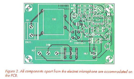
Mounting the components onto the PCB should be quite straightforward. Start by fitting the single wire bridge next to rectifier Bl. Ensure that all polarized components (diodes, LEDs, capacitors and the IC) are fitted the correct way round. The LED leads should be trimmed so that when it is soldered to the board it protrudes through a hole in the lid when the case is assembled; alternatively use a translucent enclosure.
Once all components have been fitted and all solder connections have been inspected the PCB can be fitted into an insulated enclosure. The mains input lead will require some form of strain relief. Be aware that some tracks carry lethal voltages. All appropriate safety guidelines must therefore be adhered to. A small hole can be made in the lid directly over preset PI if it is necessary to adjust the sensitivity of the circuit without dismantling the unit. Lastly,don’t forget to add perforations in the case so that sound waves can reach the microphone capsule.
Reprinted Url Of This Article: http://www.seekic.com/blog/project_solutions/2011/08/17/Intelligent_Clap_Switch__manual_remote_control_with_extras_(2).html
Print this Page | Comments | Reading(1288)
Article Categories
New published articles
· Imagination works with TSMC to develop FinFET process
Author:Ecco Reading(30194)
· XMOS pushes event-driven MCUs with lower price
Author:Ecco Reading(3462)
· Intel brings upgraded 32-nm SoC for smartphones
Author:Ecco Reading(3181)
· Micron pushes TLC 128-Gbit NAND flash
Author:Ecco Reading(3662)
· Intel will stop supplying desktop motherboards
Author:Ecco Reading(5231)
· Processor market was expected to regain strength in 2013
Author:Ecco Reading(3248)
· It was reported that TSMC sales fall steeply
Author:Ecco Reading(3390)
· Cisco, NXP work with auto wireless startup
Author:Ecco Reading(3530)
· Micron was impacted by manufacturing glitch
Author:Ecco Reading(3936)
· China can make 22-nm transistor by themselves
Author:Ecco Reading(3707)
· Chip market rebound is coming, according to survey
Author:Ecco Reading(3678)
· Sony, Toshiba will spend more on chips, iSuppli reports
Author:Ecco Reading(3714)
· Qualcomm becomes the 13th company to join NFC Forum board
Author:Ecco Reading(6028)
· TSMC increases building work for FinFET fab
Author:Ecco Reading(3692)
· TI plans to cut 1,700 jobs in OMAP shift
Author:Ecco Reading(4478)