

Project Solutions
Wireless Connectivity: ISM, WLAN, WMAN, Bluetooth et al. 5
Published:2011/8/18 2:35:00 Author:Amy From:SeekIC
Stefan Tauschek
More bandwidth
This means we need more bandwidth and more channels. The standardization committee satisfied this need in 1999 with the introduction of the 802.1 la standard. It utilizes the 5.8-GHz ISM bond and employs a modulation technique called ’orthogonal frequency division multiplexing’ (OFDM). This yields o raw data rate of 54 Mbit/s, although the range is only half as large. The total available bandwidth allocated lo this band is 455 MHz, from 5.150 GHz to 5.725 GHz. Up lo 19 non-over lapping channels are available, allowing the same number of access points to be used without mutual interference. Two years ago, the OFDM modulation technique was also introduced for the 2.4-GHz band via the 802.11g standard (2.4-GHz OFDM PHY). This means there are presently three ’air interfaces’ available - 802.11a, 802.11b and 802.11g - but they are to be replaced by 802.1 1 n in the future. The objective is to further increase the data rate to mare than 300 Mbit/s. This bit of magic is supposed to be achieved by using transmission protocols with greater efficiency, compression techniques, and receivers with improved dynamic characteristics (Table 2). 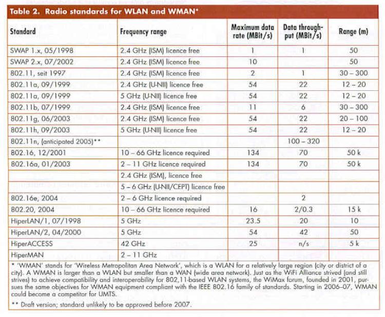
Smart antennas
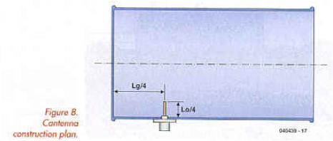
The Cantenna shows that it’s not that difficult to make antennas with good performance for centimeter-wave signals. Even so, it’s still common practice to use rod antennas with unidirectional characteristics, with the result that most of the emitted RF energy goes unused. That may be a reasonable approach for mobile systems, but in fixed installations the transmission distance con be considerably increased by using directional antennas. There are several ’classic’ antenna designs that yield directional characteristics, such as Yagi antennas and dipole arrays. However, a much simpler solution is a waveguide closed at one end, in which a standing wave is generated by suitable mechanical dimensioning. Figure 8 shows (he basic design of such a ’tin<an’ antenna. Here U is the length of the standing wave in the antenna {with the maximum being located at La/4), and Lo is the wavelength of the carrier frequency in free space. The size of the tin and the frequency jointly determine the length of the standing wave. Instructions for building a Cantenna like this and the calculation of L can be found on numerous Internet sites, such as http://www.lumpoint.net/wirelss/cantennahowto.hlml and http://www.saunalahti.fi/elepal/anienno2.hlml. With careful construction, it is certainly possible lo achieve a respectable antenna gain. Measurements show that the range can be increased by at least a factor of two.
Reprinted Url Of This Article: http://www.seekic.com/blog/project_solutions/2011/08/18/Wireless_Connectivity__ISM_WLAN_WMAN_Bluetooth_et_al_5.html
Print this Page | Comments | Reading(1360)
Article Categories
New published articles
· Imagination works with TSMC to develop FinFET process
Author:Ecco Reading(30199)
· XMOS pushes event-driven MCUs with lower price
Author:Ecco Reading(3462)
· Intel brings upgraded 32-nm SoC for smartphones
Author:Ecco Reading(3182)
· Micron pushes TLC 128-Gbit NAND flash
Author:Ecco Reading(3662)
· Intel will stop supplying desktop motherboards
Author:Ecco Reading(5233)
· Processor market was expected to regain strength in 2013
Author:Ecco Reading(3249)
· It was reported that TSMC sales fall steeply
Author:Ecco Reading(3390)
· Cisco, NXP work with auto wireless startup
Author:Ecco Reading(3531)
· Micron was impacted by manufacturing glitch
Author:Ecco Reading(3936)
· China can make 22-nm transistor by themselves
Author:Ecco Reading(3708)
· Chip market rebound is coming, according to survey
Author:Ecco Reading(3678)
· Sony, Toshiba will spend more on chips, iSuppli reports
Author:Ecco Reading(3715)
· Qualcomm becomes the 13th company to join NFC Forum board
Author:Ecco Reading(6029)
· TSMC increases building work for FinFET fab
Author:Ecco Reading(3693)
· TI plans to cut 1,700 jobs in OMAP shift
Author:Ecco Reading(4479)