

Project Solutions
RFID Detector for 13.56 MHz: Spot RFID tag transmitters from a distance 2
Published:2011/8/22 22:43:00 Author:Amy From:SeekIC
Gert Baars
A dedicated receiver
The detuning and resonance effects mentioned above take place at relatively small distances from the transmitter, say, two meters or less depending on TX power and antennas used. To be able to spot an active 13.56-MHz RFID transmitter from a greater distance we obviously need a sensitive receiver and a pickup antenna that’s as small as possible. Here, a super heterodyne receiver is used in combination with an etched microstrip antenna. Our design is not suitable for 134 kHz RFID systems.
The circuit diagram in Figure 1 is happily uncluttered arid does not contain a microcontroller or any other black-box element. The central part is an NEB 15 (or SA615) integrated circuit, IC1. Referring to the block diagram of the IC in Figure 2 we’ll explain the operation of the receiver. For convenience, the pinout of the 20-pin DIP version of the IC is also shown. 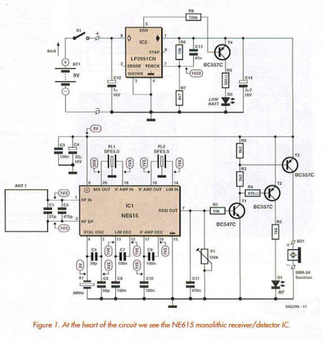
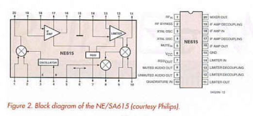
The SA615, says Philips, is a high performance monolithic low-power FM IF system incorporating a mixer/oscillator, two limiting intermediate frequency amplifiers, a quadrature detector, muting, logarithmic received signal strength indicator (RSSI) and voltage regulator. If the type code sounds vaguely familiar we bet that’s due to the ’615 combining the functions of the famous NE/SA602/612 double-balanced mixer and the NE/SA604 demodulator chip. As compared with the NE/SA605 the NE/SA615 features, among other plus points, a higher mixer input intercept point and higher IF bandwidth (25 MHz).
The NE/SA605 and NE/SA615 are functionally identical but the ’615 has improved specifications in some respects (see SA615 datasheet).
The KF1D transmitter signal is picked up by a closed loop antenna made from PCB tracks. Together with tuning capacitors CI and C2 we’re looking at a miniature magnetic loop antenna. The balanced antenna signal is applied straight away to the mixer inside the NE/SA615. The oscillator input of the mixer (refer to Figure 2) receives an 8-MHz signal obtained from quartz crystal XI. The difference frequency obtained from the mixer is 13.56 - 8 = 5.56 MHz. which is taken through a 5.5 MHz ceramic filter (normally used for TV sound subcarrier systems). The filter’s bandwidth of about 300 kHz is sufficient to receive signals between about 13.350 MHz and 13.650 MHz. which nicely covers our target frequency of 13.560 MHz. The output signal of the IF amplifier inside the NE/SA615 (pin 16) is applied to another 5.5 MHz ceramic filter, FL2, for additional suppression of unwanted mixer products. The limiter inside the SA/NE615 (input: pin 14) also amplifies the IF signal. Referring back to Figure 2, both filtered amplifier signals are applied to the RSSI circuit which serves to tell us the signal strength of the RFID transmitter.
The RSSI output (pin 7) supplies a current between 0 and 80/jA as a measure of the received signal strength. The relationship is logarithmic allowing large signals to be measured too. This allows us to equip our detector with two activity outputs: a LED, Dl and a buzzer for far away and nearby RFID transmitters respectively.
The demodulator in the NE/SA615 is simply not required so we need not waste any words or even external parts on it.
The detector’s trigger level can be set to personal requirements using preset PI. In practice, it should be set to maximum sensitivity, i.e., the LED should just not come on when you’re sure there isn’t an active RFID TX for miles around. None the less, powerful SW stations or man-made noise around 13.5 MHz may cause the LED to fight occasionally. The adjustable threshold also allows a lower battery voltage (after several hours of use) to be compensated.
The receiver has a simple power supply consisting mainly of a low-drop regulator LP2951 whose low-battery indicator signal is used to light an LED when the battery voltage drops below about 6 V.
The current consumption of the receiver in standby (non-activated) state is about 8 mA from the 9-volt PP3 battery.
Reprinted Url Of This Article: http://www.seekic.com/blog/project_solutions/2011/08/22/RFID_Detector_for_1356_MHz__Spot_RFID_tag_transmitters_from_a_distance_2.html
Print this Page | Comments | Reading(6611)
Article Categories
New published articles
· Imagination works with TSMC to develop FinFET process
Author:Ecco Reading(30322)
· XMOS pushes event-driven MCUs with lower price
Author:Ecco Reading(3466)
· Intel brings upgraded 32-nm SoC for smartphones
Author:Ecco Reading(3187)
· Micron pushes TLC 128-Gbit NAND flash
Author:Ecco Reading(3670)
· Intel will stop supplying desktop motherboards
Author:Ecco Reading(5241)
· Processor market was expected to regain strength in 2013
Author:Ecco Reading(3253)
· It was reported that TSMC sales fall steeply
Author:Ecco Reading(3395)
· Cisco, NXP work with auto wireless startup
Author:Ecco Reading(3534)
· Micron was impacted by manufacturing glitch
Author:Ecco Reading(3940)
· China can make 22-nm transistor by themselves
Author:Ecco Reading(3713)
· Chip market rebound is coming, according to survey
Author:Ecco Reading(3681)
· Sony, Toshiba will spend more on chips, iSuppli reports
Author:Ecco Reading(3719)
· Qualcomm becomes the 13th company to join NFC Forum board
Author:Ecco Reading(6034)
· TSMC increases building work for FinFET fab
Author:Ecco Reading(3698)
· TI plans to cut 1,700 jobs in OMAP shift
Author:Ecco Reading(4483)