

Project Solutions
RFID Detector for 13.56 MHz: Spot RFID tag transmitters from a distance 3
Published:2011/8/22 23:56:00 Author:Amy From:SeekIC
Gert Baars
Construction
The receiver is built on the printed circuit board shown in Figure 3. The board is single-sided and no problems are expected in the construction department as only regular-size components are used at the ’top’ side and a few SMD caps at the solder side. Also, there are no inductors to wind! 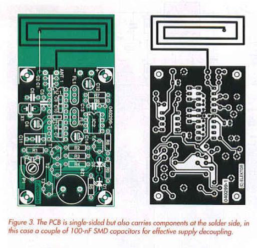
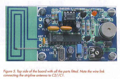
The SMD capacitors at the solder side of the board have to be fitted first. The positive aspect of their small size is their extremely effective decoupling abilities while also allowing the board size to be kept to a minimum. The SMDs may be seen in the photo of the solder side of the board, Figure 4. The top side of the board with all the components fitted appears in Figure 5. 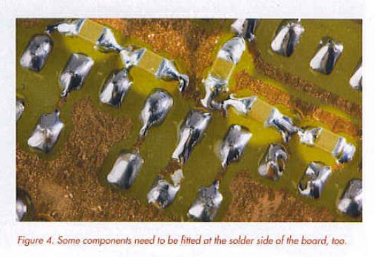
Quite satisfied with the results obtained we plan to apply ’SMD caps tor decoupling at the solder side’ more often in future Elektor projects, so it may be good idea to buy a small stock of 0805-size 100μF capacitors. If you object to the use of SMDs altogether then solder on a couple of miniature ceramic C’s instead.
The NE/SA615 is best soldered onto the board rather than inserted in a socket. The quartz crystal is preferably a low-profile type.
The photographs underline our strong advice to fit the receiver in a metal case, with the loop antenna of course protruding from a slot. A type 1590 diecast case from Hammond will also allow the battery to be secured internally with Velcro. Plenty of room, too, for the on-off switch or pushbutton.
Test, use, customization
Using a dip meter we were able to make the LED light at several meters distance horn the detector. The buzzer started to sound when we approached the detector to about 10 cms. RFID transmitters with gate-type antennas can be relied upon to supply much stronger signals so you should be able to detect their presence and activity from quite a distance — a nice highstreet pastime while the missus does the shopping The values of R2 and R3 are subject to experimentation if you want different LED; buzzer activation thresholds.
The antenna may be carefully tuned to resonance at 13.56 MHz by tweaking the capacitance across it (C1//C2). This is conveniently done with the aid of a grid dipper or a square wave generator and monitoring the voltage developed across PI (RSSI output). If your function generator does not reach up to 13.6 MHz then set it to a frequency of which 13.56 MHz is an odd harmonic (like 2.712 MHz or 4.52 MHz), terminate the generator output with its nominal impedance in series with a few turns of stiff insulated wire formed into a small loop. Hold this loop close to the detector’s antenna and increase the generator output level until an RSSI indication is obtained. Now work on the capacitor(s) until the received level maximizes.
Finally, advanced users may want to try out a larger surface antenna to get even higher sensitivity. A window antenna with a size of 75 x 75 mm tuned with a capacitance of about 500μF is a good starting point. A much simpler variant, two telescopic or whip aerials of about 1 metre in length may also give surprising results. Both variants are, of course, less suitable for covert operation.
Note
The RFID receiver described in this article is intended for educational or scientific use only. It will sound on alarm if a nearby, active 13.56-MHz transmitter is detected, which may indicate the presence of a (hidden) RFID tag of the active of passive type.
Reprinted Url Of This Article: http://www.seekic.com/blog/project_solutions/2011/08/22/RFID_Detector_for_1356_MHz__Spot_RFID_tag_transmitters_from_a_distance_3.html
Print this Page | Comments | Reading(3899)
Article Categories
New published articles
· Imagination works with TSMC to develop FinFET process
Author:Ecco Reading(30004)
· XMOS pushes event-driven MCUs with lower price
Author:Ecco Reading(3456)
· Intel brings upgraded 32-nm SoC for smartphones
Author:Ecco Reading(3178)
· Micron pushes TLC 128-Gbit NAND flash
Author:Ecco Reading(3648)
· Intel will stop supplying desktop motherboards
Author:Ecco Reading(5225)
· Processor market was expected to regain strength in 2013
Author:Ecco Reading(3242)
· It was reported that TSMC sales fall steeply
Author:Ecco Reading(3385)
· Cisco, NXP work with auto wireless startup
Author:Ecco Reading(3525)
· Micron was impacted by manufacturing glitch
Author:Ecco Reading(3932)
· China can make 22-nm transistor by themselves
Author:Ecco Reading(3701)
· Chip market rebound is coming, according to survey
Author:Ecco Reading(3673)
· Sony, Toshiba will spend more on chips, iSuppli reports
Author:Ecco Reading(3708)
· Qualcomm becomes the 13th company to join NFC Forum board
Author:Ecco Reading(6023)
· TSMC increases building work for FinFET fab
Author:Ecco Reading(3686)
· TI plans to cut 1,700 jobs in OMAP shift
Author:Ecco Reading(4473)