

Project Solutions
VHF FM Antenna Booster: New horizons in 3-metre band DXing 2
Published:2011/8/23 2:28:00 Author:Amy From:SeekIC
N. S. Hori Sankar VU3NSH
Construction
The amplifier is built on the single-sided printed circuit board shown in Figure 2. The inductors in the design are all very simple to make, see the parts list for construction details. LI, 1.2 and L3, are wound on a 4.5-mm dia. drill or pencil. LI then needs to be stretched to a length of about 10 mm. You’ll find that a relatively large resistor is needed to wind choke L4 on — we used a 0.5-watt carbon-film resistor from the junkbox (metal film resistors seem to have taken over completely). The value 1 Mil is uncritical, what we’re after is ’a lot’ of carbon tor the core so 820 k or 1.2 M will do just as well. 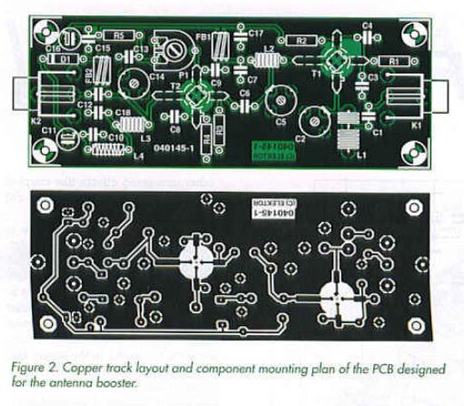
The DG-MOSFETs are not only sensitive to static discharges but also easy to fit the wrong way around. The non-SMD versions require 5-rum holes t be drilled In the PCB. Make absolutely sure you know each MOSFET’s final orientation on the board before soldering it in place — check, think hard and refer to the component drawing shown in Figure 1. You may find that the legs ate a bit too long for the PCB but don’t use your cutters until the very last moment because without the stud marker (source terminal) you will be lost for device orientation.
Several VHF/UHF DG-MOSFETs may be used in this circuit — see Table 1. With some dexterity it is also possible to use SMD devices. In general, you should aim to use a BF9xx with a low noise figure, although that may imply a slightly reduced overall gain. Remember, however, that the amplifier’s gain is secondary to the noise figure — in practice, any gain between 25 dB and 40 dB will be just fine. 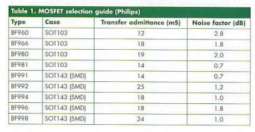
The power supply parts rue not accommodated on a PCB but may be connected up using flying lead construction in a small case.
The finished PC should be cleaned with isopropyl alcohol to remove solder residu.
The amplifier must be housed in a metal case with proper coax connectors used for Kl and K2. The author used F-type sockets as customary with satellite TV rigs. They are cheap and easy to obtain. However, BNC sockets may be used equally well. The connections between the sockets and the amplifier input and output should be kept as short as possible using thin coax cable like RG174/U.
Reprinted Url Of This Article: http://www.seekic.com/blog/project_solutions/2011/08/23/VHF_FM_Antenna_Booster__New_horizons_in_3_metre_band_DXing_2.html
Print this Page | Comments | Reading(1712)
Article Categories
New published articles
· Imagination works with TSMC to develop FinFET process
Author:Ecco Reading(30013)
· XMOS pushes event-driven MCUs with lower price
Author:Ecco Reading(3456)
· Intel brings upgraded 32-nm SoC for smartphones
Author:Ecco Reading(3178)
· Micron pushes TLC 128-Gbit NAND flash
Author:Ecco Reading(3649)
· Intel will stop supplying desktop motherboards
Author:Ecco Reading(5225)
· Processor market was expected to regain strength in 2013
Author:Ecco Reading(3242)
· It was reported that TSMC sales fall steeply
Author:Ecco Reading(3385)
· Cisco, NXP work with auto wireless startup
Author:Ecco Reading(3525)
· Micron was impacted by manufacturing glitch
Author:Ecco Reading(3932)
· China can make 22-nm transistor by themselves
Author:Ecco Reading(3701)
· Chip market rebound is coming, according to survey
Author:Ecco Reading(3673)
· Sony, Toshiba will spend more on chips, iSuppli reports
Author:Ecco Reading(3708)
· Qualcomm becomes the 13th company to join NFC Forum board
Author:Ecco Reading(6023)
· TSMC increases building work for FinFET fab
Author:Ecco Reading(3686)
· TI plans to cut 1,700 jobs in OMAP shift
Author:Ecco Reading(4473)