AD5933

Features: `100 kHz max excitation output`Impedance range 0.1 k to 10 M, 12-bit resolution`Selectable system clock from the following:`RC oscillator, external clock`DSP real and imaginary calculation (DFT)`3 V/5 V power supply`Programmable sinewave output`Frequency resolution 27 bits (<0.1 Hz)`F...

product image

AD5933 Picture
SeekIC No. : 004269552 Detail

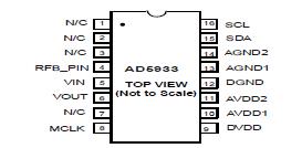
AD5933: Features: `100 kHz max excitation output`Impedance range 0.1 k to 10 M, 12-bit resolution`Selectable system clock from the following:`RC oscillator, external clock`DSP real and imaginary calculation...

floor Price/Ceiling Price

Part Number:
AD5933
Supply Ability:
5000

Price Break

  • Qty
  • 1~5000
  • Unit Price
  • Negotiable
  • Processing time
  • 15 Days
Total Cost: $ 0.00

SeekIC Buyer Protection PLUS - newly updated for 2013!

  • Escrow Protection.
  • Guaranteed refunds.
  • Secure payments.
  • Learn more >>

Month Sales

268 Transactions

Rating

evaluate  (4.8 stars)

Upload time: 2024/5/6

Payment Methods

All payment methods are secure and covered by SeekIC Buyer Protection PLUS.

Notice: When you place an order, your payment is made to SeekIC and not to your seller. SeekIC only pays the seller after confirming you have received your order. We will also never share your payment details with your seller.
Product Details

Description


Features:

`100 kHz max excitation output
`Impedance range 0.1 k to 10 M, 12-bit resolution
`Selectable system clock from the following:
`RC oscillator, external clock
`DSP real and imaginary calculation (DFT)
`3 V/5 V power supply
`Programmable sinewave output
`Frequency resolution 27 bits (<0.1 Hz)
`Frequency sweep capability with serial I2C loading
`12-Bit sampling ADC
`ADC sampling 1 MSPS, INL ± 1 LSB max
`On-chip temp sensor allows ±2 °C accuracy
`Temperature range −40°C to +125°C
`16 lead SSOP package


Application

·Complex impedance measurement
·Corrosion monitoring
·Impedance spectrometry
·Biomedical and automotive sensors
·Proximity sensors
·DFT processing


Pinout

  Connection Diagram


Specifications

Parameter Rating
VDD to GND −0.3 V to +7. 0 V
Digital Input Voltage to GND −0.3 V to VDD + 0.3 V
VOUT to GND −0.3 V to VDD + 0.3 V
Vin to GND −0.3 V to VDD + 0.3 V
Operating Temperature Range
Extended Industrial (Y grade)
−40°C to +125°C
Storage Temperature Range −65°C to +160°C
Maximum Junction Temperature 150°C
150°C
uSOIC Package
JA Thermal Impedance
JC Thermal Impedance
332°C/W
120°C/W
Lead Temperature, Soldering
Vapor Phase (60 sec)
Infrared (15 sec)
215°C
220°C
ESD 2.0 kV

Stresses above those listed under Absolute Maximum Ratings may cause permanent damage to the device. This is a stress rating only; functional operation of the device at these or any other conditions above those listed in the operational sections of this specification is not implied. Exposure to absolute maximum rating conditions for extended periods may affect device reliability.


Description

The AD5933 is a high precision impedance converter system solution which combines an on board frequency generator with a 12 Bit 1MSPS ADC. The requency generator allows an external complex impedance to be excited with a known frequency. The response signal from the impedance is sampled by the on board ADC and DFT processed by an on-board DSP engine. The DFT algorithm returns a Real (R) and imaginary (I) data word at each output frequency. This magnitude of these data words must be further scaled by calibrated Gain Factor in order to return the actual impedance value at each frequency point. The magnitude of the impedance and relative phase of the impedance at each frequency point along the sweep is easily
calculated using the following equations:
Magnitude= R2+ I2 Phase =Tan -1(I /R)

To determine the value of the unknown impedance Z(w), generally a frequency sweep is performed. The impedance can be calculated at each point and an impedance profile i.e. frequency vs. magnitude plot can be created. The system allows the user to program a 2 V p-p sinusoidal signal as excitation to an external load. Output voltage excitation ranges of 1 V, 400 mV, 200 mV can also be programmed. The signal is provided on chip using DDS techniques. Frequency resolution of 27 bits (less than 0.1HZ) can be achieved using this method. To perform the frequency sweep, the user must first program the conditions required for the sweep; start frequency, step frequency, and number of incremental points along the sweep into onboard registers. Once the relevant registers have been programmed, a Start Command to the control register is required in order to begin the sweep. To determine the impedance of the load at any one frequency point, Z(w), a measurement system comprised of a transimpedance amplifier, gain stage, and ADC are used to record data. The gain stage for the response stage is 1 or 5. At each point on the sweep the ADC will take 1024 samples and calculate a Discrete Fourier Transform to provide the real and imaginary data for the response signal waveform. The real and imaginary data stored in memory and is available to the user through the 12C interface. The ADC is a low noise; high speed 1 MSPS sampling ADC that operates from 3 V supply. Clocking for both the DDS and ADC signals is provided externally via the MCLK reference clock, which is provided externally from a crystal oscillator or system clock or by use of the internal RC oscillator. The AD5933 is available in a 16 lead SSOP.


Customers Who Bought This Item Also Bought

Margin,quality,low-cost products with low minimum orders. Secure your online payments with SeekIC Buyer Protection.
Power Supplies - External/Internal (Off-Board)
Audio Products
Power Supplies - Board Mount
Connectors, Interconnects
Optoelectronics
Batteries, Chargers, Holders
View more