CD4541B

Features: • Low Symmetrical Output Resistance, Typically 100Ω at VDD = 15V• Built-In Low-Power RC Oscillator• Oscillator Frequency Range . . . . . . . . . . DC to 100kHz• External Clock (Applied to Pin 3) can be Used Instead of Oscillator• Operates as 2N Frequen...

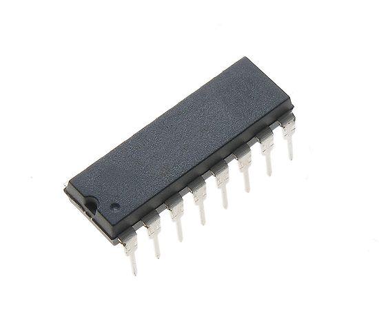
product image

CD4541B Picture
SeekIC No. : 004311428 Detail

CD4541B: Features: • Low Symmetrical Output Resistance, Typically 100Ω at VDD = 15V• Built-In Low-Power RC Oscillator• Oscillator Frequency Range . . . . . . . . . . DC to 100kHz̶...

floor Price/Ceiling Price

Part Number:
CD4541B
Supply Ability:
5000

Price Break

  • Qty
  • 1~5000
  • Unit Price
  • Negotiable
  • Processing time
  • 15 Days
Total Cost: $ 0.00

SeekIC Buyer Protection PLUS - newly updated for 2013!

  • Escrow Protection.
  • Guaranteed refunds.
  • Secure payments.
  • Learn more >>

Month Sales

268 Transactions

Rating

evaluate  (4.8 stars)

Upload time: 2024/4/28

Payment Methods

All payment methods are secure and covered by SeekIC Buyer Protection PLUS.

Notice: When you place an order, your payment is made to SeekIC and not to your seller. SeekIC only pays the seller after confirming you have received your order. We will also never share your payment details with your seller.
Product Details

Description


Features:

• Low Symmetrical Output Resistance, Typically 100Ω at VDD = 15V
• Built-In Low-Power RC Oscillator
• Oscillator Frequency Range . . . . . . . . . . DC to 100kHz
• External Clock (Applied to Pin 3) can be Used Instead of Oscillator
• Operates as 2N Frequency Divider or as a Single-Transition Timer
• Q/Q Select Provides Output Logic Level Flexibility
• AUTO or MASTER RESET Disables Oscillator During Reset to Reduce Power Dissipation
• Operates With Very Slow Clock Rise and Fall Times
• Capable of Driving Six Low Power TTL Loads, Three Low-Power Schottky Loads, or Six HTL Loads Over the Rated Temperature Range
• Symmetrical Output Characteristics
• 100% Tested for Quiescent Current at 20V
• 5V, 10V, and 15V Parametric Ratings
• Meets All Requirements of JEDEC Standard No. 13B, "Standard Specifications for Description of 'B' Series CMOS Devices"


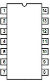
Pinout

  Connection Diagram


Specifications

DC Supply - Voltage Range, VDD
  Voltages Referenced to VSS Terminal   . . . . . . . . . . -0.5V to +20V
Input Voltage Range, All Inputs  . . . . . . . . . . .  -0.5V to VDD +0.5V
DC Input Current, Any One Input . . . . . . . . . . . . . . . . . . . . .±10mA
Device Dissipation Per Output Transistor
  For TA = Full Package Temperature Range
  (All Package Types)  . . . . . . . . . . . . . . . . . . . . . . . . . . . . . 100mW


Description

CD4541B programmable timer consists of a 16-stage binary counter, an oscillator that is controlled by external R-C compo- nents (2 resistors and a capacitor), an automatic power-on reset circuit, and output control logic. The counter increments on positive-edge clock transitions and can also be reset via the MASTER RESET input.

The output from this timer is the Q or Q output from the 8th, 10th, 13th, or 16th counter stage. The desired stage is chosen using time-select inputs A and B (see Frequency Select Table). The output is available in either of two modes selectable via the MODE input, pin 10 (see Truth Table).When this MODE input is
a logic "1", the CD4541B output will be a continuous square wave having a frequency equal to the oscillator frequency divided by 2N. With the CD4541B MODE input set to logic "0" and after a MASTER RESET is initiated, the output (assuming Q output has been selected) changes from a low to a high state after 2N-1 counts
and remains in that state until another MASTER RESET pulse is applied or the MODE input is set to a logic "1".

CD4541B Timing is initialized by setting the AUTO RESET input (pin 5) to logic "0" and turning power on. If pin 5 is set to logic "1", the AUTO RESET circuit is disabled and counting will not start until after a positive MASTER RESET pulse is applied and returns to a low level. The AUTO RESET consumes an appreciable amount of power and should not be used if low-power operation is desired. For reliable automatic power-on reset, VDD should be greater than 5V.

The CD4541B RC oscillator, shown in Figure 2, oscillates with a frequency determined by the RC network and is calculated using:


Customers Who Bought This Item Also Bought

Margin,quality,low-cost products with low minimum orders. Secure your online payments with SeekIC Buyer Protection.
Transformers
Industrial Controls, Meters
Soldering, Desoldering, Rework Products
Motors, Solenoids, Driver Boards/Modules
Resistors
View more