Features: ` 2-V to 6-V VCC Operation ('HC190, 191)
` 4.5-V to 5.5-V VCC Operation ('HCT191)
` Wide Operating Temperature Range of −55°C to 125°C
` Synchronous Counting and Asynchronous Loading
` Two Outputs for n-Bit Cascading
` Look-Ahead Carry for High-Speed Counting
` Balanced Propagation Delays and Transition Times
` Standard Outputs Drive Up To 15 LS-TTL Loads
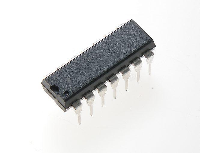
` Significant Power Reduction Compared to LS-TTL Logic ICsPinout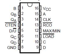 Specifications
Supply voltage range, VCC . . . . . . . . . . . . . . . . . . . . . . . . . . . . . . −0.5 V to 7 V
Input clamp current, IIK (VI < 0 or VI > VCC) (see Note 1) . . . . . . . . . . ±20 mA
Output clamp current, IOK (VO < 0 or VO > VCC) (see Note 1) . . . . . . . ±20 mA
Continuous output drain current per output, IO (VO = 0 to VCC) . . . . . .±35 mA
Continuous output source or sink current per output, IO (VO = 0 to VCC) . ±25 mA
Continuous current through VCC or GND . . . . . . . . . . . . . . . . . . . . . . . . ±50 mA
Package thermal impedance, JA (see Note 2): E package . . . . . . . . . 67°C/W
M package . . . . . . . . . . . . . . . . . . . . . . . . . . . . . . . . . . 73°C/W
NS package . . . . . . . . . . . . . . . . . . . . . . . . . . . . . . . . . 64°C/W
PW package . . . . . . . . . . . . . . . . . . . . . . . . . . . . . . . .108°C/W
Storage temperature range, Tstg . . . . . . . . . −65°C to 150°C
† Stresses beyond those listed under "absolute maximum ratings" may cause permanent damage to the device. These are stress ratings only, and functional operation of the device at these or any other conditions beyond those indicated under "recommended operating conditions" is not implied. Exposure to absolute-maximum-rated conditions for extended periods may affect device reliability.
NOTES: 1. The input and output voltage ratings may be exceeded if the input and output current ratings are observed.
2. The package thermal impedance is calculated in accordance with JESD 51-7.
DescriptionThe CD54/74HC190 are asynchronously presettable BCD decade counters, whereas the CD54/74HC191 and CD54/74HCT191 are asynchronously presettable binary counters.
Presetting the CD54/74HC190 counter to the number on preset data inputs (A−D) is accomplished by a low asynchronous parallel load (LOAD) input. CD54/74HC190 Counting occurs when LOAD is high, count enable (CTEN) is low, and the down/up (D/U) input is either high for down counting or low for up counting. The counter is decremented or incremented synchronously with the low-to-high transition of the clock.
When an overflow or underflow of the counter occurs, the MAX/MIN output, CD54/74HC190 is low during counting, goes high and remains high for one clock cycle. This output can be used for look-ahead carry in high-speed cascading (see Figure 1). The MAX/MIN output also initiates the ripple clock (RCO) output, which normally is high, goes low, and remains low for the low-level portion of the clock pulse. These CD54/74HC190 counters can be cascaded using RCO (see Figure 2).
If a decade counter is preset to an illegal state or assumes an illegal state when power is applied, CD54/74HC190 returns to the normal sequence in one or two counts, as shown in the state diagrams (see Figure 3).

 CD74HCT191 Data Sheet