CD74HCT299

Features: • Buffered Inputs• Four Operating Modes: Shift Left, Shift Right, Load and Store• Can be Cascaded for N-Bit Word Lengths• I/O0 - I/O7 Bus Drive Capability and Three-State for Bus Oriented Applications• Typical fMAX = 50MHz at VCC = 5V, CL = 15pF, TA = 25oC&#...

product image

CD74HCT299 Picture
SeekIC No. : 004312140 Detail

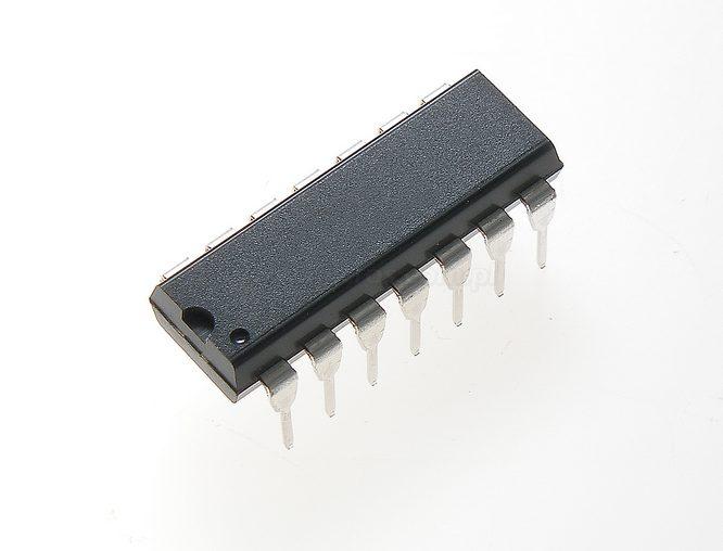
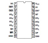
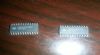
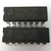
CD74HCT299: Features: • Buffered Inputs• Four Operating Modes: Shift Left, Shift Right, Load and Store• Can be Cascaded for N-Bit Word Lengths• I/O0 - I/O7 Bus Drive Capability and Three...

floor Price/Ceiling Price

Part Number:
CD74HCT299
Supply Ability:
5000

Price Break

  • Qty
  • 1~5000
  • Unit Price
  • Negotiable
  • Processing time
  • 15 Days
Total Cost: $ 0.00

SeekIC Buyer Protection PLUS - newly updated for 2013!

  • Escrow Protection.
  • Guaranteed refunds.
  • Secure payments.
  • Learn more >>

Month Sales

268 Transactions

Rating

evaluate  (4.8 stars)

Upload time: 2024/4/18

Payment Methods

All payment methods are secure and covered by SeekIC Buyer Protection PLUS.

Notice: When you place an order, your payment is made to SeekIC and not to your seller. SeekIC only pays the seller after confirming you have received your order. We will also never share your payment details with your seller.
Product Details

Description


Features:

• Buffered Inputs
• Four Operating Modes: Shift Left, Shift Right, Load and Store
• Can be Cascaded for N-Bit Word Lengths
• I/O0 - I/O7 Bus Drive Capability and Three-State for Bus Oriented Applications
• Typical fMAX = 50MHz at VCC = 5V, CL = 15pF, TA = 25oC
• Fanout (Over Temperature Range)
   - Standard Outputs . . . . . . . . . . . . . . . 10 LSTTL Loads
   - Bus Driver Outputs . . . . . . . .  . . . .   . 15 LSTTL Loads
• Wide Operating Temperature Range . . . -55oC to 125oC
• Balanced Propagation Delay and Transition Times
• Significant Power Reduction Compared to LSTTL Logic ICs
• HC Types
   - 2V to 6V Operation
   - High Noise Immunity: NIL = 30%, NIH = 30% of VCC at VCC = 5V
• HCT Types
  - 4.5V to 5.5V Operation
  - Direct LSTTL Input Logic Compatibility,VIL= 0.8V (Max), VIH = 2V (Min)
  - CMOS Input Compatibility, Il 1A at VOL, VOH


Pinout

  Connection Diagram


Specifications

DC Supply Voltage, VCC            . . . . . . . . . . . . . . . . . . . . . . . . -0.5V to 7V
DC Input Diode Current, IIK
   For VI < -0.5V or VI > VCC + 0.5V     . . . . . . . . . . . . . . . . . . . . . .±20mA
DC Output Diode Current, IOK
   For VO < -0.5V or VO > VCC + 0.5V       . . . . . . . . . . . . . . . . . . . .±20mA
DC Drain Current, per Output, IO, For -0.5V < VO < VCC + 0.5V
   For Q Outputs . . . . . . . . . . . . . . . . . . . . . . . . . . . . . . . . . . . . . . .±25mA
   For I/O Outputs . . . . . . . . . . . . . . . . . . . . . . . . . . . . . . . . . . . . . .±35mA
DC Output Source or Sink Current per Output Pin, IO
   For VO > -0.5V or VO < VCC + 0.5V        . . . . . . . . . . . . . . . . . . . .±25mA
DC VCC or Ground Current, ICC . . . . . . . .      . . . . . . . . . . . . . . . . .±50mA


Description

The 'HC259 and 'HCT299 are 8-bit shift/storage registers with three-state bus interface capability. The register has four synchronous-operating modes controlled by the two select
inputs as shown in the mode select (S0, S1) table. The mode select, the serial data (DS0, DS7) and the parallel data (I/O0- I/O7) respond only to the low-to-high transition of the clock (CP) pulse. S0, S1 and data inputs must be stable one setup time prior to the clock positive transition.
CD74HCT299 Master Reset (MR) is an asynchronous active low input.When MR output is low, the register is cleared regardless of the status of all other inputs. The register can be expanded
by cascading same units by tying the serial output (Q0) to CD74HCT299 serial data (DS7) input of the preceding register, and tying CD74HCT299 serial output (Q7) to the serial data (DS0) input of
the following register. Recirculating the (n x 8) bits is accomplished by tying the Q7 of the last stage to the DS0 of the first stage.
The three-state input/output I(/O) port has three modes of operation:
1. Both CD74HCT299 output enable (OE1 and OE2) inputs are low and S0 or S1 or both are low, the data  in the register is presented at the eight outputs.
2. When CD74HCT299 both S0 and S1 are high, I/O terminals are in the high impedance state but being input ports, ready for parallel data to be loaded into eight registers with one clock transition regardless of the status ofOE1 and OE2.
3. Either one of the two output enable inputs being high will force I/O terminals to be in the off-state. CD74HCT299 is noted that each I/O terminal is a three-state output and a CMOS buffer input.


Customers Who Bought This Item Also Bought

Margin,quality,low-cost products with low minimum orders. Secure your online payments with SeekIC Buyer Protection.
Batteries, Chargers, Holders
Line Protection, Backups
Fans, Thermal Management
Optoelectronics
Transformers
Potentiometers, Variable Resistors
View more