CDP1020

Features: • Fully Compliant with Device Bay Specification 0.90 and ACPI Specification 1.0• Industry Standard SMBus/I2C Interface• Controls for Two Device Bays• Onboard Level Shifting for Direct Drive of N-Channel MOSFET VID Switches• Integrated Pull-up Resistors on 13...

product image

CDP1020 Picture
SeekIC No. : 004312424 Detail

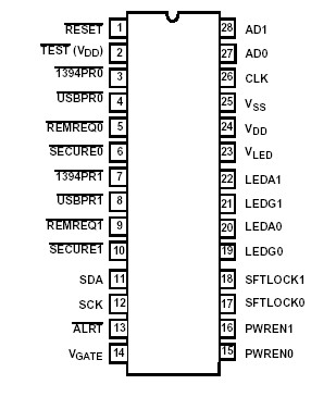
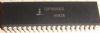
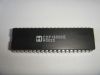
CDP1020: Features: • Fully Compliant with Device Bay Specification 0.90 and ACPI Specification 1.0• Industry Standard SMBus/I2C Interface• Controls for Two Device Bays• Onboard Level ...

floor Price/Ceiling Price

Part Number:
CDP1020
Supply Ability:
5000

Price Break

  • Qty
  • 1~5000
  • Unit Price
  • Negotiable
  • Processing time
  • 15 Days
Total Cost: $ 0.00

SeekIC Buyer Protection PLUS - newly updated for 2013!

  • Escrow Protection.
  • Guaranteed refunds.
  • Secure payments.
  • Learn more >>

Month Sales

268 Transactions

Rating

evaluate  (4.8 stars)

Upload time: 2024/4/27

Payment Methods

All payment methods are secure and covered by SeekIC Buyer Protection PLUS.

Notice: When you place an order, your payment is made to SeekIC and not to your seller. SeekIC only pays the seller after confirming you have received your order. We will also never share your payment details with your seller.
Product Details

Description


Features:

• Fully Compliant with Device Bay Specification 0.90 and ACPI Specification 1.0
• Industry Standard SMBus/I2C Interface
• Controls for Two Device Bays
• Onboard Level Shifting for Direct Drive of N-Channel MOSFET VID Switches
• Integrated Pull-up Resistors on 1394PRx, USBPRx, SECUREx, and REMREQx Inputs
• RC Type Oscillator - Low Cost and Low Power Consumption
• Operational Voltage from 3.3 to 5.5V
• "5V Tolerant" Inputs at all Operating Voltages
• Write-Once BIOS/External Configuration
• Removal Request Input for Each Bay
• Security Lock Input for Each Bay
• High Current Device Bay LED Indicator Drivers With Separate High-Side Power Input
• Configurable Level/Pulse Bay Solenoid Drivers
• Programmable Insertion Time Out Delay
• HCMOS Technology; 28 Lead Plastic SOIC


Pinout

  Connection Diagram


Specifications

Supply Voltage, VDD . . . . . . . . . . . . . . . . . . . .. . . . . . -0.5V to +6V
Supply Voltage, VGATE . . . . . . . . . . . . . . . . . . . . . . . . . VDD to 13V
Supply Voltage, VLED . . . . . . . . . . . . . . . . . . . . . . . . . -0.5V to +6V
Input Voltage, VIN . . . . . . . . . . . . . . . . . . VSS - 0.3V to VDD + 0.3V
Test Mode, VIN . . . . . . . . . . . . . . .  . . VSS - 0.3V to 2 x VDD + 0.3V
Current Drain Per Pin Excluding VDD and VSS, I . . . . . . . . . . 40mA


Description

The CDP1020 is an ACPI compliant Device Bay Controller (DBC) that can control two device bays. The controller interfaces to the host system through the industry standard I2C or System Management Bus (SMBus) and is fully compliant with Device Bay Specification 0.90. The CDP1020 is designed to be compatible with the integrated SMBus host controller of the PiiX4/PiiX6 in Intel Architecture platforms.

The CDP1020 is designed to be placed on the host motherboard, on a riser, or adjacent to the Device Bay connectors. The required clock source is generated from an internal oscillator on the CLK pin, with an external RC to set the frequency. This lowers the system cost and allows the CDP1020 to remain active during S3-S5 system states where all clock generators have been stopped.

One of the key features of this device is the on-chip level shifters that provide slew rate controlled, direct gate drive for external N-Channel MOSFETs (Intersil HUF76113DK8 recommended) to switch the device bay VID supplies. Switching an N-Channel device as opposed to a P-Channel reduces both device cost and device count, resulting in an overall lower system cost.

Configuration data for the CDP1020, including subsystem vendor ID, subsystem revision, bay size and device bay capabilities are designed to be written into the CDP1020 by the system BIOS at power up. The registers for this data are write-once-only and thus become read-only after the initial BIOS write.

The address selection pins (AD1 and AD0) allow the CDP1020 to occupy any one of four I2C/SMBus addresses. This enables up to four CDP1020 devices to coexist in a system.

The CDP1020 implements high current outputs for direct drive (with a limiting resistor) of the optional bay status LEDs. These indicators are two color (green/amber) common anode or anti-parallel LEDs that indicate the device bay status per the Device Bay Specification 0.90.


Customers Who Bought This Item Also Bought

Margin,quality,low-cost products with low minimum orders. Secure your online payments with SeekIC Buyer Protection.
Discrete Semiconductor Products
Programmers, Development Systems
Memory Cards, Modules
Power Supplies - External/Internal (Off-Board)
Industrial Controls, Meters
Potentiometers, Variable Resistors
View more