Maximum Operating Temperature
: + 150 C
Packaging
: Tube
Configuration
: Single
Maximum Gate Emitter Voltage
: +/- 20 V
Collector- Emitter Voltage VCEO Max
: 1200 V
Continuous Collector Current at 25 C
: 13 A
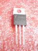
Package / Case
: TO-220AB-3
Gate-Emitter Leakage Current
: +/- 250 nA
Collector-Emitter Saturation Voltage
: 2.05 V
Power Dissipation
: 104 W
Features: • 13A, 1200V, TC = 25oC
• 1200V Switching SOA Capability
• Typical Fall Time. . . . . . . . . . . . . . . . 360ns at TJ = 150oC
• Short Circuit Rating
• Low Conduction Loss
• Avalanche Rated
• Temperature Compensating SABER™ Model
Thermal Impedance SPICE Model
www.intersil.com
• Related Literature
- TB334 "Guidelines for Soldering Surface Mount
Components to PC Boards"Pinout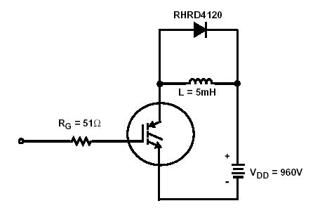 SpecificationsCollector to Emitter Voltage . . . . . . . . . . . . . . . . . . . . . . . . . . . . . . . . . .BVCES 1200 V
Collector Current Continuous
At TC = 25. . . . . . . . . . . . . . . . . . . . . . . . . . . . . . . . . . . . . . . . . . . . . .. . . . IC25 13 A
At TC = 110 . . . . . . . . . . . . . . . . . . . . . . . . . . . . . . . . . . . . . . . . . . . . . . . . IC110 7 A
Collector Current Pulsed (Note 1) . . . . . . . . . . . . . . . . . . . . . . . . . . . . . . . . . ICM 20 A
Gate to Emitter Voltage Continuous. . . . . . . . . . . . . . . . . . . . . . . . . . . . . .VGES ±20 V
Gate to Emitter Voltage Pulsed . . . . . . . . . . . . . . . . . . . . . . . . . . . . . . . . VGEM ±30 V
Switching Safe Operating Area at TJ = 150 (Figure 2) . . . . . . .. . SSOA 13A at 1200V
Power Dissipation Total at TC = 25 . . . . . . . . . . . . . . . . . . . . . . . . . . . . . .. PD 104 W
Power Dissipation Derating TC > 25 . . . . . . . . . . . . . . . . . . . . . . . . . . . . . . 0.83 W/
Forward Voltage Avalanche Energy (Note 2) . . . . . . . . . . . . . . . . . . . . . . . .. EAV 18 mJ
Operating and Storage Junction Temperature Range . . . . . . . . . TJ, TSTG -55 to 150
Maximum Lead Temperature for Soldering
Leads at 0.063in (1.6mm) from case for 10s . . . . . . . . . . . . . . . . . . . . . . . . . TL 300
Package Body for 10s, see Tech Brief 334 . . . . . . . . . . . . . . . . . . . . . . . . . .Tpkg 260
Short Circuit Withstand Time (Note 3) at VGE = 15V. . . . . . . . . . . . . . . . . . . . . .tSC 8 µsDescriptionThe HGTD2N120CNS, HGTP2N120CN, and HGT1S2N120CNS are Non-Punch Through (NPT) IGBT designs. HGTD2N120CNS, HGTP2N120CN, and HGT1S2N120CNS are new members of the MOS gated high voltage switching IGBT family. IGBTs combine the best features of MOSFETs and bipolar transistors. This device has the high input impedance of a MOSFET and the low on-state conduction loss of a bipolar transistor.
The HGTD2N120CNS, HGTP2N120CN, and HGT1S2N120CNS IGBT is ideal for many high voltage switching applications operating at moderate frequencies where low conduction losses are essential, such as: AC and DC motor controls, power supplies and drivers for solenoids, relays and contactors.Formerly Developmental Type TA49313.

 HGTP2N120CN Data Sheet