Product
:
Operating Supply Voltage
:
Mounting Style
: SMD/SMT
Packaging
: Tube
Package / Case
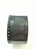
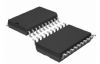
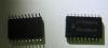
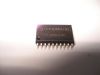
: SOIC-20 Wide
Type
: Full Bridge Motor Driver
Supply Current
: 1.5 mA
Features: • Two Independent Controlled Complementary MOS Power Output Half H-Drivers (Full-Bridge) for Nominal 3V to 12V Power Supply Operation
• Split ±Voltage Power Supply Option for Output Drivers
• Load Switching Capabilities to 0.5A
• Single Supply Range +2.5V to +15V
• Low Standby Current
• CMOS/TTL Compatible Input Logic
• Over-Temperature Shutdown Protection
• Overcurrent Limit Protection
• Overcurrent Fault Flag Output
• Direction, Braking and PWM Control
• Pb-Free Plus Anneal Available (RoHS Compliant)
Application• DC Motor Driver
• Relay and Solenoid Drivers
• Stepper Motor Controller
• Air Core Gauge Instrument Driver
• Speedometer Displays
• Tachometer Displays
• Remote Power Switch
• Battery Operated Switch Circuits
• Logic and Microcontroller Operated SwitchPinout SpecificationsSupply Voltage; VDD to VSS or VSSA or VSSB . . . . . . . . . . . . . +15V
Neg. Output Supply Voltage, (VSSA, VSSB) . . . . . . . . . . . . (Note 1)
DC Logic Input Voltage (Each Input) . . . (VSS -0.5V) to (VDD +0.5V)
DC Logic Input Current (Each Input) . . . . . . . . . . . . . . . . . . ±15mA
ILF Fault Output Current . . . . . . . . . . . . . . . . . . . . . . . . . . ±15mA
Output Load Current, (Self Limiting, See Elec. Spec.). . . .±IO(LIMIT)DescriptionIn the Functional Block Diagram of the HIP4020, the four switches and a load are arranged in an H-Configuration so that the drive voltage from terminals OUTA and OUTB can be cross-switched to change the direction of current flow in the load. HIP4020, is commonly known as 4-quadrant load control. As shown in the Block Diagram, switches Q1 and Q4 are conducting or in an ON state when current flows from VDD through Q1 to the load, and then through Q4 to terminal VSSB; where load terminal OUTA is at a positive potential with respect to OUTB. Switches Q1 and Q4 are operated synchronously by the control logic. The control logic switches Q3 and Q2 to an open or OFF state when Q1 and Q4 are switched ON. To reverse the current flow in the load, the switch states are reversed where Q1 and Q4 are OFF while Q2 and Q3 are ON. Consequently, current then flows from VDD through Q3, through the load, and through Q2 to terminal VSSA, and load terminal OUTB is then at a positive potential with respect to OUTA.
Terminals ENA and ENB are ENABLE Inputs for the Logic A and B Input Controls. The ILF output of HIP4020, is an Overcurrent Limit Fault Flag Output and indicates a fault condition for either Output A or B or both. The VDD and VSS are the Power Supply reference terminals for the A and B Control Logic Inputs and ILF Output. While the VDD positive power supply terminal is internally connected to each bridge driver, the VSSA and VSSB Power Supply terminals are separate and independent from VSS and may be more negative than the VSS ground reference terminal. The use of level shifters in the gate drive circuitry to the NMOS (low-side) output stages allows controlled level shifting of the output drive relative to ground.
Parameters: | Technical/Catalog Information | HIP4020IB |
| Vendor | Intersil |
| Category | Integrated Circuits (ICs) |
| Configuration | H Bridge |
| Voltage - Supply | 3 V ~ 12 V |
| Current - Peak | 625mA |
| Delay Time | 2.5s |
| Package / Case | 20-SOIC |
| Packaging | Tube |
| Number of Outputs | 4 |
| Input Type | Inverting and Non-Inverting |
| Number of Configurations | 1 |
| Operating Temperature | -40°C ~ 85°C |
| High Side Voltage - Max (Bootstrap) | - |
| Lead Free Status | Contains Lead |
| RoHS Status | RoHS Non-Compliant |
| Other Names | HIP4020IB
HIP4020IB
|

 HIP4020IB Data Sheet