LMV358DUAL

Features: `2.7-V and 5-V Performance`No Crossover Distortion`Low Supply Current: LMV321 . . . 130 A Typ LMV358 . . . 210 A Typ LMV324 . . . 410 A Typ`Rail-to-Rail Output Swing`Package Options Include Plastic Small-Outline (D), Small-Outline Transistor (SOT-23 DBV, SC-70 DCK), and Thin Shrink Small...

product image

LMV358DUAL Picture
SeekIC No. : 004397249 Detail

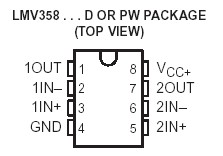
LMV358DUAL: Features: `2.7-V and 5-V Performance`No Crossover Distortion`Low Supply Current: LMV321 . . . 130 A Typ LMV358 . . . 210 A Typ LMV324 . . . 410 A Typ`Rail-to-Rail Output Swing`Package Options Includ...

floor Price/Ceiling Price

Part Number:
LMV358DUAL
Supply Ability:
5000

Price Break

  • Qty
  • 1~5000
  • Unit Price
  • Negotiable
  • Processing time
  • 15 Days
Total Cost: $ 0.00

SeekIC Buyer Protection PLUS - newly updated for 2013!

  • Escrow Protection.
  • Guaranteed refunds.
  • Secure payments.
  • Learn more >>

Month Sales

268 Transactions

Rating

evaluate  (4.8 stars)

Upload time: 2024/4/19

Payment Methods

All payment methods are secure and covered by SeekIC Buyer Protection PLUS.

Notice: When you place an order, your payment is made to SeekIC and not to your seller. SeekIC only pays the seller after confirming you have received your order. We will also never share your payment details with your seller.
Product Details

Description


Features:

`2.7-V and 5-V Performance
`No Crossover Distortion
`Low Supply Current:
      LMV321 . . . 130 A Typ
      LMV358 . . . 210 A Typ
      LMV324 . . . 410 A Typ
`Rail-to-Rail Output Swing
`Package Options Include Plastic Small-Outline (D), Small-Outline Transistor (SOT-23 DBV, SC-70 DCK), and Thin Shrink Small-Outline (PW) Packages


Pinout

  Connection Diagram


Specifications

Supply voltage, VCC (see Note 1) . . . . . . . . . . . . . . . . . . . . . . . . . . . . . . . . . . . . . . .5.5 V
Differential input voltage, VID (see Note 2)  . . . . . . . . . . . . . . . . . . . . . . . . . . . . . .±5.5 V
Input voltage, VI (either input)  . . . . . . . . . . . . . . . . . . . . . . . . . . . . . . . . . . . . .0 to 5.5 V
Duration of output short circuit (one amplifier) to ground at (or below) TA = 25,
VCC 3 5.5 V (see Note 3)  . . . . . . . . . . . . . . . . . . . . . . . . . . . . . . . . . . . . . . . . .. Unlimited
Operating virtual junction temperature . . . . . . . . . . . . . . . . . . . . . . . . . . . . . . .. . . .150
Package thermal impedance, qJA (see Notes 4 and 5): D (8-pin) package  . . .  . .197/W
                                                                                      D (14-pin) package  . . . ..127/W
                                                                                      DBV package  . . . . . . . .  .347/W
                                                                                      DCK package  . . . . . . . .  .389/W
                                                                                      PW (8-pin) package  . . .. .243/W
                                                                                      PW (14-pin) package  . .  . 170/W
Lead temperature 1,6 mm (1/16 inch) from case for 10 seconds: D or PW package  . 260
                                                                                                      DBV or DCK package  TBD
Storage temperature range, Tstg  . . . . . . . . . . . . . . . . . . . . . . . . . . . . . . . . ...65 to 150
† Stresses beyond those listed under "absolute maximum ratings" may cause permanent damage to the device. These are stress ratings only, and functional operation of the device at these or any other conditions beyond those indicated under "recommended operating conditions" is not implied. Exposure to absolute-maximum-rated conditions for extended periods may affect device reliability.
NOTES: 1. All voltage values (except differential voltages and VCC specified for the measurement of IOS) are with respect to the network GND.
2. Differential voltages are at IN+ with respect to IN.
3. Short circuits from outputs to VCC can cause excessive heating and eventual destruction.
4. Maximum power dissipation is a function of TJ(max), JA, and TA. The maximum allowable power dissipation at any allowable ambient temperature is PD = (TJ(max) TA)/JA. Selecting the maximum of 150 can impact reliability.
5. The package thermal impedance is calculated in accordance with JESD 51.


Description

The LMV324 and LMV358DUAL are low-voltage (2.7 V to 5.5 V) versions of the dual and quad operational amplifiers, LM324 and LM358, that operate from 5 V to 30 V. The LMV321 is the single-amplifier version.

The LMV321, LMV324, and LMV358DUAL are the most cost-effective solutions for applications where low-voltage operation, space saving, and low price are needed. They offer specifications that meet or exceed those of the familiar LM358 and LM324 devices. These devices have rail-to-rail output-swing capability, and the input common-mode voltage range includes ground. They all exhibit excellent speed-to-power ratios, achieving 1MHz of bandwidth at 1-V/ms slew rate with low supply current.

The LMV321 is available in the ultra-small DCK package, which is approximately one-half the size of the DBV package. This package saves space on printed circuit boards and enables the design of small portable electronic devices. It also allows the designer to place the device closer to the signal source to reduce noise pickup and increase signal integrity.

The LMV321I, LMV324I, and LMV358DUAL devices are characterized for operation from 40 to 85.


Customers Who Bought This Item Also Bought

Margin,quality,low-cost products with low minimum orders. Secure your online payments with SeekIC Buyer Protection.
Optical Inspection Equipment
Power Supplies - External/Internal (Off-Board)
Boxes, Enclosures, Racks
Transformers
View more