ApplicationThe LV8572A can be used in a single power supply application. To achieve this, the VBB pin must be connected to ground, and the power connected to VCC and PFAIL pins. The Oscillator Failed/Single Supply bit in the Periodic Flag Register should be set to a logic 1, which will disable the oscillator battery reference circuit. The power fail interrupt
should also be disabled. This will turn off the linear power fail detection circuits, and will eliminate any quiescent power drawn through these circuits. Until the crystal select bits are initialized, the LV8572A may consume about 50 A due to arbitrary oscillator selection at power on.
(This extra 50 A is not consumed if the battery backed mode is selected).
Pinout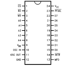 SpecificationsSpecifications for the 883 version of this product are listed separately.
Supply Voltage (VCC) ............................0.5V to a7.0V
DC Input Voltage (VIN) ...................0.5V to VCC a0.5V
DC Output Voltage (VOUT) .............0.5V to VCC a 0.5V
Storage Temperature Range.................65 to a150
Power Dissipation (PD)................................... 500 mW
Lead Temperature (Soldering, 10 sec.)............... 260DescriptionThe LV8572A is intended for use in microprocessor based systems where information is required for multi-tasking, data logging or general time of day/date information. This device is implemented in low voltage silicon gate microCMOS technology to provide low standby power in battery back-up environments. The circuit's architecture is such that it looks like a contiguous block of memory or I/O ports. The LV8572A address space is organized as 2 software selectable pages of 32 bytes. This includes the Control Registers, the Clock Counters, the Alarm Compare RAM, and the Time Save RAM. Any of the RAM locations that are not being used for their intended purpose may be used as general purpose CMOS RAM.
Time and date are maintained from 1/100 of a second to year and leap year in a BCD format, 12 or 24 hour modes. Day of week, day of month and day of year counters are provided. Time is controlled by an on-chip crystal oscillator requiring only the addition of the crystal and two capacitors. The choice of crystal frequency is program selectable. Power failure logic and control functions have been integrated on chip. This logic is used by the RTC to issue a power fail interrupt, and lock out the p interface. The time power fails may be logged into RAM automatically when VBB> VCC. Additionally, two supply pins are provided. When VBB > VCC, internal circuitry will automatically switch from the main supply to the battery supply. Status bits are provided by LV8572A to indicate initial application of battery power, system power, and low battery detect. (Continued)

 LV8572A Data Sheet


