Features: • Output Drive Capability: 10 LSTTL Loads
• Outputs Directly Interface to CMOS, NMOS, and TTL
• Operating Voltage Range: 2 to 6 V
• Low Input Current: 1 A
• High Noise Immunity Characteristic of CMOS Devices
• In Compliance with the Requirements Defined by JEDEC Standard No 7A
• Chip Complexity: 244 FETs or 61 Equivalent GatesApplicationEach half of the MC54/74HC390A has independent ÷ 2 and ÷ 5 sections (except for the Reset function). The ÷ 2 and ÷ 5 counters can be connected to give BCD or biquinary (25) count sequences. If Output QA is connected to the
Clock B input (Figure 4), a decade divider with BCD output is obtained. The function table for the BCD count sequence is given in Table 1.
To obtain a biquinary count sequence, the input signals connected to the Clock B input, and output QD is connected
to the Clock A input (Figure 5). QA provides a 50% duty cycle output. The biquinary count sequence function table is
given in Table 2.
Pinout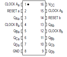 Specifications
|
Symbol |
Parameter |
Value |
Unit |
|
VCC |
DC Supply Voltage (Referenced to GND) |
0.5 to +7.0 |
V |
|
Vin |
DC Input Voltage (Referenced to GND) |
0.5 to VCC +0.5 |
V |
|
Vout |
DC Output Voltage (Referenced to GND) |
0.5 to VCC + 0.5 |
V |
|
Iin |
DC Input Current, per Pin |
± 20 |
mA |
|
|
DC Output Current, per Pin |
± 25 |
mA |
|
ICC |
DC Supply Current, VCC and GND Pins |
± 50 |
mA |
|
PD |
Power Dissipation in Still Air, Plastic or Ceramic DIP†
SOIC Package†
TSSOP Package† |
750
500
450 |
mW |
|
Tstg |
Storage Temperature |
65 to + 150 |
|
|
TL |
Lead Temperature, 1 mm from Case for 10 Seconds
(Plastic DIP, SOIC or TSSOP Package)
(Ceramic DIP)
|
260
300 |
|
*Maximum Ratings are those values beyond which damage to the device may occur.Functional operation
should be restricted to the Recommended Operating Conditions.
†Derating - Plastic DIP: 10 mW/ from 65 ° to 125
Ceramic DIP: 10 mW/ from 100 ° to 125
SOIC Package: 7 mW/ from 65 ° to 125
TSSOP Package: 6.1 mW/�C from 65� to 125�C
For high frequency or heavy load considerations, see Chapter 2 of the Motorola HighSpeed CMOS Data Book (DL129/D).
This device contains protection circuitry to guard against damage due to high static voltages or electric fields.However, precautions must be taken to avoid applications of any voltage higher than maximum rated voltages to this highimpedance circuit. For proper operation, Vin and Vout should be constrained to the range GND (Vin or Vout) VCC.
Unused inputs must always be tied to an appropriate logic voltage level (e.g., either GND or VCC). Unused outputs must be left open.
DescriptionThe MC54/74HC390A is identical in pinout to the LS390. The device inputs are compatible with standard CMOS outputs; with pullup resistors, they are compatible with LSTTL outputs.
MC54/74HC390A consists of two independent 4bit counters, each composed of a dividebytwo and a dividebyfive section. The dividebytwo and dividebyfive counters have separate clock inputs, and MC54/74HC390A can be cascaded to implement various combinations of ÷ 2 and/or ÷ 5 up to a ÷ 100 counter.
Flipflops internal to the counters of MC54/74HC390A are triggered by hightolow transitions of the clock input. A separate, asynchronous reset is provided for each 4bit counter. State changes of the Q outputs do not occur simultaneously because of internal ripple delays. Therefore, decoded output signals of MC54/74HC390A are subject to decoding spikes and should not be used as clocks or strobes except when gated with the Clock of the HC390A.

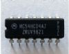
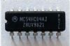
 MC54HC390A Data Sheet