MNADC12062M-X

Features: ·Built-in sample-and-hold·Single +5V supply·Single channel or 2 channel multiplexer operation·Low Power Standby mode KEY SPECIFICATIONS·Sampling rate 1 MHz (min)·Conversion time 740 nS (typ)·Signal-to-Noise Ratio, fin = 100 kHz 69.5 dB (min)·Power dissipation (fs = 1MHz) 75 mW (max)·No m...

product image

MNADC12062M-X Picture
SeekIC No. : 004424735 Detail

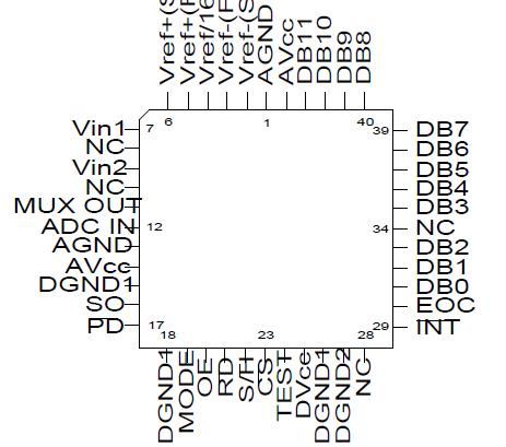
MNADC12062M-X: Features: ·Built-in sample-and-hold·Single +5V supply·Single channel or 2 channel multiplexer operation·Low Power Standby mode KEY SPECIFICATIONS·Sampling rate 1 MHz (min)·Conversion time 740 nS (ty...

floor Price/Ceiling Price

Part Number:
MNADC12062M-X
Supply Ability:
5000

Price Break

  • Qty
  • 1~5000
  • Unit Price
  • Negotiable
  • Processing time
  • 15 Days
Total Cost: $ 0.00

SeekIC Buyer Protection PLUS - newly updated for 2013!

  • Escrow Protection.
  • Guaranteed refunds.
  • Secure payments.
  • Learn more >>

Month Sales

268 Transactions

Rating

evaluate  (4.8 stars)

Upload time: 2024/5/13

Payment Methods

All payment methods are secure and covered by SeekIC Buyer Protection PLUS.

Notice: When you place an order, your payment is made to SeekIC and not to your seller. SeekIC only pays the seller after confirming you have received your order. We will also never share your payment details with your seller.
Product Details

Description


Features:

· Built-in sample-and-hold
· Single +5V supply
· Single channel or 2 channel multiplexer operation
· Low Power Standby mode KEY SPECIFICATIONS
· Sampling rate 1 MHz (min)
· Conversion time 740 nS (typ)
· Signal-to-Noise Ratio, fin = 100 kHz 69.5 dB (min)
· Power dissipation (fs = 1MHz) 75 mW (max)
· No missing codes over temperature Guaranteed


Application

· Digital signal processor front ends
· Instrumentation
· Disk drives
· Mobile telecommunications
· Waveform digitizers


Pinout

  Connection Diagram


Specifications

Supply Voltage (Vcc = DVcc = AVcc)................. -0.3V to +6V
Voltage at Any Input or Output..............-0.3V to Vcc + 0.3V
Input Current at Any Pin
(Note 3).......................................................................25mA
Package Input Current
(Note 3).......................................................................50mA
Power Dissapation
(Note 4)....................................................................875mW
ESD Susceptibility
(Note 5).....................................................................1500V
Soldering Information
(10 seconds) .............................................................300 C
Storage Temperature Range......................-65 C to +150 C
Maximum Junction Temperature
(Tjmax)...................................................................... 150 C
Thermal Resistance
ThetaJA
(Still Air) ..................................................................45 C/W
(500LF/Min Air flow) ................................................27 C/W
ThetaJC ..................................................................7.5 C/W
Note 1: Absolute Maximum Ratings indicate limits beyond which damage to the device may occur. Operating Ratings indicate conditions for which the device is functional, but do not guarantee specific performance limits. For guaranteed specifications and test conditions, see the Electrical Characteristics. The guaranteed specifications apply only for the test conditions listed. Some performance characteristics may degrade when the device is not operated under the listed test conditions.
Note 2: All voltages are measured with respect to Gnd (Gnd = Agnd = Dgnd), unless otherwise specified.
Note 3: When the input voltage (Vin) at any pin exceeds the power supply rails (Vin < Gnd or Vin > Vcc) the absolute value of current at that pin should be limited to 25mA or less. The 50mA package input current limits the number of pins that can safely exceed the power supplies with an input current of 25mA to two.
Note 4: The maximum power dissipation must be derated at elevated temperatures and is dictated by Tjmax, ThetaJA and the ambient temperature TA. The maximum allowable power dissipation at any temperature is Pd = (Tjmax - TA)/ThetaJA or the number given in the absolute maximum ratings, whichever is lower. In most cases the maximum derated power dissipation will be reached only during fault conditions.
Note 5: Human body model, 100pF discharged through a 1.5K Ohm resistor.


Description

Using an innovative multistep conversion technique, the 12-bit ADC12062 CMOS analog-to-digital converter digitizes signals at a 1MHz sampling rate while consuming a maximum of only 75mW on a single +5V supply. The ADC12062 performs a 12-bit conversion in three lower-resolution "flash" conversions, yielding a fast A/D without the cost and power dissipation associated with true flash approaches.

The analog input voltage to the ADC12062 is tracked and held by an internal sampling circuit, allowing high frequency input signals to be accurately digitized without the need for an external sample-and-hold circuit. The ADC12062 multiplexer output is available to the user in order to perform additional external signal processing before the signal is digitized  When the converter is not digitizing signals, it can be placed in the Standby mode; typical power consumption in this mode is 100uW.


Customers Who Bought This Item Also Bought

Margin,quality,low-cost products with low minimum orders. Secure your online payments with SeekIC Buyer Protection.
Cable Assemblies
Optical Inspection Equipment
Programmers, Development Systems
Power Supplies - Board Mount
Semiconductor Modules
View more