NTGS3446

Features: • Ultra Low R DS(on)• Higher Efficiency Extending Battery Life• Logic Level Gate Drive• Diode Exhibits High Speed, Soft Recovery• Avalanche Energy Specified• IDSS Specified at Elevated Temperature• Pb−Free Package is AvailableApplication...

product image

NTGS3446 Picture
SeekIC No. : 004436662 Detail

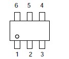
NTGS3446: Features: • Ultra Low R DS(on)• Higher Efficiency Extending Battery Life• Logic Level Gate Drive• Diode Exhibits High Speed, Soft Recovery• Avalanche Energy Specified&#...

floor Price/Ceiling Price

Part Number:
NTGS3446
Supply Ability:
5000

Price Break

  • Qty
  • 1~5000
  • Unit Price
  • Negotiable
  • Processing time
  • 15 Days
Total Cost: $ 0.00

SeekIC Buyer Protection PLUS - newly updated for 2013!

  • Escrow Protection.
  • Guaranteed refunds.
  • Secure payments.
  • Learn more >>

Month Sales

268 Transactions

Rating

evaluate  (4.8 stars)

Upload time: 2024/4/28

Payment Methods

All payment methods are secure and covered by SeekIC Buyer Protection PLUS.

Notice: When you place an order, your payment is made to SeekIC and not to your seller. SeekIC only pays the seller after confirming you have received your order. We will also never share your payment details with your seller.
Product Details

Description


Features:


• Ultra Low R DS(on)
• Higher Efficiency Extending Battery Life
• Logic Level Gate Drive
• Diode Exhibits High Speed, Soft Recovery
• Avalanche Energy Specified
• IDSS Specified at Elevated Temperature
• Pb−Free Package is Available


Application

• Power Management in portable and battery−powered products, i.e. computers, printers, PCMCIA cards, cellular and cordless
• Lithium Ion Battery Applications
• Notebook PC


Pinout

  Connection Diagram


Specifications

Rating
Symbol
Value
Unit
Drain−to−Source Voltage
VDSS
20
V
Gate−to−Source Voltage
VGS
±12
V
Thermal Resistance
Junction−to−Ambient (Note 1)
Total Power Dissipation @ TA = 25°C
Drain Current
− Continuous @ TA = 25°C
− Pulsed Drain Current (tp < 10 s)
R JA
P d
I D
I DM
244
0.5
2.5
10
°C/W
W
A
A
Thermal Resistance
Junction−to−Ambient (Note 2)
Total Power Dissipation @ TA = 25°C
Drain Current
− Continuous @ TA = 25°C
− Pulsed Drain Current (tp< 10 s)
R JA
P d
I D
I DM
128
1.0
3.6
14
°C/W
W
A
A
Thermal Resistance
Junction−to−Ambient (Note 3)
Total Power Dissipation @ TA = 25°C
Drain Current
− Continuous @ TA = 25°C
− Pulsed Drain Current (tp < 10 s)
RJA
Pd
I D
IDM
62.5
2.0
5.1
20
°C/W
W
A
A
Source Current (Body Diode)
IS
5.1
A
Operating and Storage Temperature Range
TJ, Tstg
−55 to
150
°C
Maximum Lead Temperature for Soldering
Purposes for 10 seconds
TL
260
°C

Maximum ratings are those values beyond which device damage can occur. Maximum ratings applied to the device are individual stress limit values (not normal operating conditions) and are not valid simultaneously. If these limits are exceeded, device functional operation is not implied, damage may occur and reliability may be affected.
1. Minimum FR−4 or G−10PCB, operating to steady state.
2. Mounted onto a 2" square FR−4 board (1" sq. 2 oz. cu. 0.06" thick single−sided), operating to steady state.
3. Mounted onto a 2" square FR−4 board (1" sq. 2 oz. cu. 0.06" thick single−sided), t < 5.0 seconds.


Customers Who Bought This Item Also Bought

Margin,quality,low-cost products with low minimum orders. Secure your online payments with SeekIC Buyer Protection.
Resistors
Semiconductor Modules
Sensors, Transducers
Cables, Wires - Management
Power Supplies - Board Mount
View more