Features: • High-performance RISC CPU
• Only 35 single word instructions to learn
• All single cycle instructions except for program branches which are two cycle
• Operating speed: DC - 20 MHz clock input DC - 200 ns instruction cycle
|
Device |
Memory |
Pins |
A/D
Resolution |
A/D
Channels |
|
Program
x14 |
Data
x8 |
|
PIC16C717 |
2K |
256 |
18,20 |
10 bits |
6 |
|
PIC16C770 |
2K |
256 |
20 |
12 bits |
6 |
|
PIC16C771 |
4K |
256 |
20 |
12 bits |
6 |
• Interrupt capability (up to 10 internal/external
interrupt sources)
• Eight level deep hardware stack
• Direct, indirect and relative addressing modes
• Power-on Reset (POR)
• Power-up Timer (PWRT) and Oscillator Start-up Timer (OST)
• Watchdog Timer (WDT) with its own on-chip RC oscillator for reliable operation
• Selectable oscillator options:
- INTRC - Internal RC, dual speed (4MHz and 37KHz) dynamically switchable for power savings
- ER - External resistor, dual speed (user selectable frequency and 37KHz) dynamically switchable for power savings
- EC - External clock
- HS - High speed crystal/resonator
- XT - Crystal/resonator
- LP - Low power crystal
• Low-power, high-speed CMOS EPROM technology
• In-Circuit Serial Programming™ (ISCP)
• Wide operating voltage range: 2.5V to 5.5V
• 15 I/O pins with individual control for:
- Direction (15 pins)
- Digital/Analog input (6 pins)
- PORTB interrupt on change (8 pins)
- PORTB weak pull-up (8 pins)
- High voltage open drain (1 pin)
• Commercial and Industrial temperature ranges
• Low-power consumption:
- < 2 mA @ 5V, 4 MHz
- 22.5 A typical @ 3V, 32 kHz
- < 1 A typical standby current
Peripheral Features:
• Timer0: 8-bit timer/counter with 8-bit prescaler
• Timer1: 16-bit timer/counter with prescaler,can be incremented during sleep via external crystal/clock
• Timer2: 8-bit timer/counter with 8-bit period register, prescaler and postscaler
• Enhanced Capture, Compare, PWM (ECCP) module
- Capture is 16 bit, max. resolution is 12.5 ns
- Compare is 16 bit, max. resolution is 200 ns
- PWM max. resolution is 10 bit
- Enhanced PWM:
- Single, Half-Bridge and Full-Bridge output modes
- Digitally programmable deadband delay
• Analog-to-Digital converter:
- PIC16C770/771 12-bit resolution
- PIC16C717 10-bit resolution
• On-chip absolute bandgap voltage reference generator
• Programmable Brown-out Reset (PBOR) circuitry
• Programmable Low-Voltage Detection (PLVD) circuitry
• Master Synchronous Serial Port (MSSP) with two modes of operation:
- 3-wire SPI™ (supports all 4 SPI modes)
- I2C™ compatible including master mode support
• Program Memory Read (PMR) capability for lookup table, character string storage and checksum calculation purposes
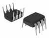
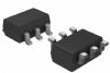
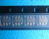
Pinout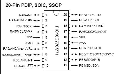 Specifications
| Program Memory Type |
OTP |
| Program Memory (KB) |
7 |
| CPU Speed (MIPS) |
5 |
| RAM Bytes |
256 |
| Digital Communication Peripherals |
1-MSSP(SPI/I2C) |
| Capture/Compare/PWM Peripherals |
1 ECCP |
| Timers |
2 x 8-bit, 1 x 16-bit |
| ADC |
6 ch, 12-bit |
| Temperature Range (C) |
-40 to 85 |
| Operating Voltage Range (V) |
2.5 to 5.5 |
| Pin Count |
20 |
Ambient temperature under bias................................................................. .-55 to +125
Storage temperature ............................................................................... -65 to +150
Voltage on any pin with respect to VSS (except VDD,MCLR and RA4)....-0.3V to (VDD + 0.3V)
Voltage on VDD with respect to VSS .............................................................. -0.3 to +7.5V
Maximum voltage between AVDD and VDD pins..................................................... ± 0.3V
Maximum voltage between AVSS and VSS pins ..................................................... ± 0.3V
Voltage on MCLR with respect to VSS........................................................ -0.3V to +8.5V
Voltage on RA4 with respect to Vss ....................................................... -0.3V to +10.5V
Total power dissipation (Note 1)..............................................................................1.0W
Maximum current out of VSS pin ..........................................................................300 mA
Maximum current into VDD pin .............................................................................250 mA
Input clamp current, IIK (VI < 0 or VI > VDD)..................................................... ± 20 mA
Output clamp current, IOK (VO < 0 or VO > VDD) .............................................. ± 20 mA
Maximum output current sunk by any I/O pin........................................................25 mA
Maximum output current sourced by any I/O pin ..................................................25 mA
Maximum current sunk by PORTA and PORTB (combined) ...................................200 mA
Maximum current sourced by PORTA and PORTB (combined)...............................200 mA
Note 1: Power dissipation is calculated as follows: Pdis = VDD x {IDD - IOH} + {(VDD - VOH) x IOH} + (VOl x IOL).
† NOTICE: Stresses above those listed under "Absolute Maximum Ratings" may cause permanent damage to the device. This is a stress rating only and functional operation of the device at those or any other conditions above thoseindicated in the operation listings of this specification is not implied. Exposure to maximum rating conditions for extended periods may affect device reliability.
DescriptionThis powerful (200 nanosecond instruction execution) yet easy-to-program (only 35 single word instructions) CMOS OTP-based 8-bit microcontroller packs Microchip's powerful PIC? architecture into an 20-pin package and is upwards compatible with the PIC16C5X and PIC12CXXX devices. The PIC16C771 features 6 channels of 12-bit Analog-to-Digital (A/D) converter giving designers the ability to discriminate smaller signal changes and eliminate the need for external circuitry for high precision measurement of analog signals. With 2 additional timers and an enhanced capture/compare/PWM function that make PIC16C771 ideal for the most sophisticated applications requiring higher levels of A/D in automotive, industrial, appliances and consumer applications.

 PIC16C771 Data Sheet