Features: ` Supports real time error detection and correction in hardware. Error correction to n = 27, error detect to n = 30 and raw data transfer to n = 32.
` CD-R to CD-n greater than 8. Internal operation is faster, but firmware and physical (laser/media) factors limit the speed
` DVD-ROM supported in combination with the SAA7335
` Direct generic interface to external Small Computer Systems Interface (SCSI) controller devices
` Operates with up to 16 Mbytes DRAM
Hyper-page DRAM up to 33 Mbytes words/s burst
Fast-page DRAM at up to 17.5 Mbytes words/s burst
` Has fixed n = 1 or n = 2 rate (44.1 or 88.2 kHz) I2S-bus multimedia output for simple audio/video output; features for CAV/quasi-CLV support
Supports Philips multimedia audio CODEC
Provides 'SHOARMA' Red Book audio buffer
` IEC 958 (SPDIF, AES/EBU and DOBM) output with Q-W subcode and programmable category code, output at n = 1 rate
` Device registers are memory mapped for faster direct
access to the chip
` Provides direct access from sub-CPU to buffer RAM to support scratchpad accesses. This eliminates the need for extra RAM chips in the system
` Automatic sequencing of ATAPI packet command protocol, including command termination
` Automated data transfers to and from the host using PIO, DMA and ultra DMA.
Pinout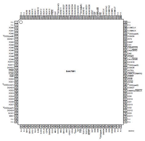 Specifications
| SYMBOL |
PARAMETER |
MIN. |
TYP. |
UNIT |
| VDDD(core) |
core digital supply voltage |
-0.5 |
+4.5 |
V |
| VDDD(pad) |
periphery digital supply voltage |
-0.5 |
+6.5 |
V |
| VDDA |
analog supply voltage |
-0.5 |
+4.6 |
V |
| Vi(max) |
maximum voltage on any input |
-0.5 |
VDDD(pad) + 0.5 |
V |
| Vo |
output voltage on any output |
-0.5 |
+6.5 |
V |
| Io |
output current (continuous) |
- |
20 |
mA |
| P |
power dissipation |
- |
400 |
mW |
| Tstg |
storage temperature |
-55 |
+125 |
°C |
| Tamb |
operating ambient temperature |
0 |
70 |
°C |
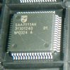
DescriptionThe SAA7391 is a block decoder/encoder and buffer manager for high-speed CD-ROM/CD-R functions, that integrates real time error correction and detection and bidirectional ATAPI transfer functions into a single chip.
2.1 Memory mapped control registers
The SAA7391 device has a large number of memory mapped registers. These are arranged so that high-level languages see the registers as external byte or 16-bit integer quantities. The block addressing of the SAA7391 facilitates the use of pairs of 16-bit quantities to represent addresses.
The reading and writing of 16-bit registers within the device can be performed by two separate 8-bit reads, where the second byte data is latched at the same time as the first byte is read.
2.2 Error correction features
The SAA7391 has an on-chip 36 kbits memory that is used as a buffer memory for error and erasure correction processing. This buffer memory reduces the number of external RAM accesses that are needed for error correction and thus allows for an increased rate of data throughput.
The error corrector is switchable between two-pass, single-pass [both with Error Detection/Correction (EDC)] and EDC only modes to further improve throughput. The presence of the full error corrector removes the need for firmware based control of the error corrector's operation.
2.3 Host interface features
The SAA7391 has an ATAPI host interface that may be directly connected to the ATAPI bus thereby reducing the need for external support devices. It supports PIO Mode 4 transfer and Mode 0 ultra DMA. This interface can also be configured as a generic DMA interface for use with external host interface devices (e.g. SCSI controller). The DMA interface has the following features:
` ATAPI command packets are automatically loaded into the command FIFO
` Data transfer to the host is automatically sequenced to reduce inter-block latencies and improve host CPU utilisation
` Host data transfer rate is independent of error corrector operation and the data input path
` The host interface features automatic determination of block length for Mode 2, Form 1 and Form 2 sectors. The block length transferred is programmable.
` The host interface can transfer up to 3 sub-blocks per sector, with each sub-block being transferred dependent on the Form bit. Automatic reload of sub-block pointers and unconditional transfer are supported.
2.4 Buffer memory organisation
Memory is mapped as a 16-bit block number and 12-bit offset into that block. The block oriented memory structure permits the use of 16-bit pointers in software thereby minimising the overhead of accessing memory.
The address can be found from the following equation: address = block number * 2560 + offset.
The microcontroller sees the SAA7391 as a memory mapped peripheral, with control and status registers appearing in the upper address space.
The lowest 52 kbytes (48 kbytes + 4 kbytes) of the 8051 microcontroller external address space is mapped as a window into the memory on a user-specified 1 kbyte boundary within the buffer RAM. This can be used as a scratchpad memory.
The next 4 kbytes is separately mapped as a window into the memory on a user-specified 1 kbyte boundary within the RAM.
The next 7.5 kbytes of the external data space consists of three independently addressed memory segments for accessing block data, subcode information and block headers.
The registers of the SAA7391 are mapped into the top 256 bytes of external data space.
2.5 Subcode handling features
The writing of data into the buffer RAM is aligned to the absolute time sync marker with the following features:
` Subcodes are written into memory together with their associated sector data.This eases the provision of specialist features, for example CD + G or Karaoke CD applications.
` All channels of subcode are de-interleaved
` The Q channel is also Cyclic Redundancy Checked (CRC) for increased reliability
` When operating in 3-wire subcode mode, it is possible to control or read the P bit in the P-W subcode stream.
2.6 Multimedia output audio control features
The I2S-bus input may be processed before feeding to the multimedia audio output in several simple ways:
` As audio is transferred via the buffer memory, it is not necessary to have the CD-DSP I2S-bus input at exactly the audio n = 1 or video n = 2 rate. Any faster speed will work because the buffer RAM is used as a FIFO.
` Both channels may be independently controlled. The left channel output may be sourced from zero (digital silence), left or right input; this also applies for the right channel output. This permits basic audio switching and channel swapping.
` IEC 958 (SPDIF, AES/EBU and DOBM) output with Q-W subcode and programmable category code, can be output from the same CD-DSP I2S-bus data source.

 SAA7391 Data Sheet