DescriptionThe SC1461 is designed as a versatile charge pump for use in bettery operated power supply applications. A simple, low current boost circuit can be implemented without costly inductors or capacitors. Internal MOSFETs and control circuitry eliminate need for costly board space and design...
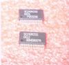
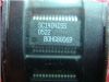
SC1461: DescriptionThe SC1461 is designed as a versatile charge pump for use in bettery operated power supply applications. A simple, low current boost circuit can be implemented without costly inductors or...
SeekIC Buyer Protection PLUS - newly updated for 2013!
268 Transactions
All payment methods are secure and covered by SeekIC Buyer Protection PLUS.
The SC1461 is designed as a versatile charge pump for use in bettery operated power supply applications. A simple, low current boost circuit can be implemented without costly inductors or capacitors. Internal MOSFETs and control circuitry eliminate need for costly board space and design time. The small device footprint allows for compact circuit design.
SC1461 has five features. (1)Small size 5 pin SOT-23 package. (2)4% voltage accuracy. (3)65uA typical quiescent current. (4)User selectable output voltages of 1.515Vin, 1.32Vin, or adjustable output. (5)All specifications rated over full temperature range (-40°C to 85°C). Those are all the main features.
Some absolute maximum ratings of SC1461 have been concluded into several points as follow. (1)Its supply voltage would be from -0.3V to 4V. (2)Its output voltage would be from -0.3V to 6V. (3)Its thermal resistance junction to ambient would be 410°C/W. (4)Its operating temperature range would be form -40°C to 85°C. (5)Its temperature range would be from -40°C to 125°C. (6)Its storage temperature range would be from -65°C to 150°C. (7)Its lead temperature soldering 10 seconds would be 300°C. It should be noted that stresses above those listed in absolute maximum ratings may cause permanent damage to device.
Also some electrical characteristics of SC1461 are concluded as follow. (1)Its input supply voltage would be min 2.25V and max 3.63V. (2)Its input supply current would be typ 65uA and max 100uA at DISABLE=GND. (3)Its output voltage would be min -4% and max 4%. (4)Its output current would be min 7mA and typ 8mA at ADJ=Vin=2.5V and DISABLE=GND. (5)Its efficiency would be typ 50%. (6)Its oscillator frequency would be typ 12MHz at ADJ=Vin=2.5V and DISABLE=GND and it would be typ 13.5MHz at ADJ, DISABLE=GND and Vin=3.3V. (7)Its disable current would be typ 1uA and max 10uA. And so on. If you have any question or suggestion or want to know more information please contact us for details. Thank you!