SN74AHCT174

Features: ` EPICE (Enhanced-Performance Implanted CMOS) Process` Inputs Are TTL-Voltage Compatible` Contain Six Flip-Flops With Single-Rail Outputs` Applications Include: Buffer/Storage Registers Shift Registers Pattern Generators` Latch-Up Performance Exceeds 250 mA Per JESD 17` ESD Protection Ex...

product image

SN74AHCT174 Picture
SeekIC No. : 004498025 Detail

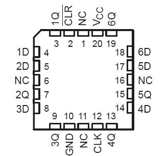
SN74AHCT174: Features: ` EPICE (Enhanced-Performance Implanted CMOS) Process` Inputs Are TTL-Voltage Compatible` Contain Six Flip-Flops With Single-Rail Outputs` Applications Include: Buffer/Storage Registers Sh...

floor Price/Ceiling Price

Part Number:
SN74AHCT174
Supply Ability:
5000

Price Break

  • Qty
  • 1~5000
  • Unit Price
  • Negotiable
  • Processing time
  • 15 Days
Total Cost: $ 0.00

SeekIC Buyer Protection PLUS - newly updated for 2013!

  • Escrow Protection.
  • Guaranteed refunds.
  • Secure payments.
  • Learn more >>

Month Sales

268 Transactions

Rating

evaluate  (4.8 stars)

Upload time: 2025/12/24

Payment Methods

All payment methods are secure and covered by SeekIC Buyer Protection PLUS.

Notice: When you place an order, your payment is made to SeekIC and not to your seller. SeekIC only pays the seller after confirming you have received your order. We will also never share your payment details with your seller.
Product Details

Description


Features:

` EPICE (Enhanced-Performance Implanted
  CMOS) Process
` Inputs Are TTL-Voltage Compatible
` Contain Six Flip-Flops With Single-Rail Outputs
` Applications Include:
Buffer/Storage Registers
Shift Registers
Pattern Generators
` Latch-Up Performance Exceeds 250 mA Per JESD 17
` ESD Protection Exceeds JESD 22
2000-V Human-Body Model (A114-A)
200-V Machine Model (A115-A)
1000-V Charged-Device Model (C101)
` Package Options Include Plastic
  Small-Outline (D), Shrink Small-Outline
  (  DB), Thin Very Small-Outline (DGV), Thin
  Shrink Small-Outline (PW), and Ceramic
  Flat (W) Packages, Ceramic Chip Carriers
  (FK), and Standard Plastic (N) and Ceramic (J) DIPs


Pinout

  Connection Diagram


Specifications

Supply voltage range, VCC . . . . . . . . . . . . . . . . . . . . . . . . . . . . . . . . . . . . . . . . . . . . . . . . . . . . . . . 0.5 V to 7 V
Input voltage range, VI (see Note 1) . . . . . . . . . . . . . . . . . . . . . . . . . . . . . . . . . . . . . . . . . . . . . . . . .0.5 V to 7 V
Output voltage range, VO (see Note 1) . . . . . . . . . . . . . . . . . . . . . . . . . . . . . . . . . . . . . . .0.5 V to VCC + 0.5 V
Input clamp current, IIK (VI < 0) . . . . . . . . . . . . . . . . . . . . . . . . . . . . . . . . . . . . . . . . . . . . . . . . . . . . . . . 20 mA
Output clamp current, IOK (VO < 0 or VO > VCC) . . . . . . . . . . . . . . . . . . . . . . . . . . . . . . . . . . . . . . . . . . . ±20 mA
Continuous output current, IO (VO = 0 to VCC) . . . . . . . . . . . . . . . . . . . . . . . . . . . . . . . . . . . . . . . . . . . . ±25 mA
Continuous current through VCC or GND . . . . . . . . . . . . . . . . . . . . . . . . . . . . . . . . . . . . . . . . . . . . . . . . . ±50 mA
Package thermal impedance, qJA (see Note 2): D package . . . . . . . . . . . . . . . . . . . . . . . . . . . . . . . . . . . 73°C/W
DB package . . . . . . . . . . . . . . . . . . . . . . . . . . . . . . . . .  . . . . . . . . . .  . . . . . . . . . .  . . . . . . . . . .  . . . . . . .82°C/W
DGV package . . . . . . . . . . . . . . . . . . . . . . . . . . . . . . .  . . . . . . . . . .  . . . . . . . . . .  . . . . . . . . . .  . . . . . . .120°C/W
N package . . . . . . . . . . . . . . . . . . . . . . . . . . . . . . . . . . . . . . . . . . . .  . . . . . . . . . .  . . . . . . . . . .  . . . . . . . .67°C/W
PW package . . . . . . . . . . . . . . . . . . . . . . . . . . . . . . . .  . . . . . . . . . .  . . . . . . . . . .  . . . . . . . . . .  . . . . . . .108°C/W
Storage temperature range, Tstg . . . . . . . . . . . . . . . . . . . . . . . . . . . . . . . . . . . . . . . . . . . . . . . . . 65°C to 150°C
‡ Stresses beyond those listed under "absolute maximum ratings" may cause permanent damage to the device. These are stress ratings only, and
functional operation of the device at these or any other conditions beyond those indicated under "recommended operating conditions" is not
implied. Exposure to absolute-maximum-rated conditions for extended periods may affect device reliability.
NOTES: 1. The input and output voltage ratings may be exceeded if the input and output current ratings are observed.
2. The package thermal impedance is calculated in accordance with JESD 51.


Description

These SN54AHCT174 and SN74AHCT174 monolithic positive-edge-triggered D-type flip-flops have a direct clear (CLR) input.

Information at the data (D) inputs meeting the setup time requirements is transferred to the outputs on the positive-going edge of the clock (CLK) pulse. Clock triggering occurs at a particular voltage level and is not directly related to the transition time of the positive-going edge of CLK. When CLK is at either the high or low level, the D input has no effect at the output.In the SN54AHCT174 and SN74AHCT174 , the SN54AHCT174 is characterized for operation over the full military temperature range of 55°C to 125°C. The SN74AHCT174 is characterized for operation from 40°C to 85°C.


Customers Who Bought This Item Also Bought

Margin,quality,low-cost products with low minimum orders. Secure your online payments with SeekIC Buyer Protection.
Undefined Category
Cables, Wires - Management
Line Protection, Backups
Discrete Semiconductor Products
Test Equipment
Memory Cards, Modules
View more