SN74LVTH32237

Features: ` Member of the Texas Instruments Widebus+™Family` Output Ports Have Equivalent 22- Series Resistors, So No External Resistors Are Required` Supports Mixed-Mode Signal Operation (5-V Input and Output Voltages With 3.3-V VCC)` Supports Unregulated Battery Operation Down to 2.7 V` Ty...

product image

SN74LVTH32237 Picture
SeekIC No. : 004499494 Detail

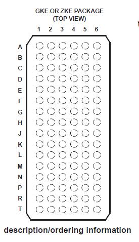
SN74LVTH32237: Features: ` Member of the Texas Instruments Widebus+™Family` Output Ports Have Equivalent 22- Series Resistors, So No External Resistors Are Required` Supports Mixed-Mode Signal Operation (5-V...

floor Price/Ceiling Price

Part Number:
SN74LVTH32237
Supply Ability:
5000

Price Break

  • Qty
  • 1~5000
  • Unit Price
  • Negotiable
  • Processing time
  • 15 Days
Total Cost: $ 0.00

SeekIC Buyer Protection PLUS - newly updated for 2013!

  • Escrow Protection.
  • Guaranteed refunds.
  • Secure payments.
  • Learn more >>

Month Sales

268 Transactions

Rating

evaluate  (4.8 stars)

Upload time: 2025/12/24

Payment Methods

All payment methods are secure and covered by SeekIC Buyer Protection PLUS.

Notice: When you place an order, your payment is made to SeekIC and not to your seller. SeekIC only pays the seller after confirming you have received your order. We will also never share your payment details with your seller.
Product Details

Description


Features:

` Member of the Texas Instruments
    Widebus+™Family
` Output Ports Have Equivalent 22- Series
     Resistors, So No External Resistors Are
      Required
` Supports Mixed-Mode Signal Operation
    (5-V Input and Output Voltages With
    3.3-V VCC)
` Supports Unregulated Battery Operation
    Down to 2.7 V
` Typical VOLP (Output Ground Bounce)
    <0.8 V at VCC = 3.3 V, TA = 25°C
` Ioff and Power-Up 3-State Support Hot
    Insertion
` Bus Hold on Data Inputs Eliminates the
    Need for External Pullup/Pulldown
    Resistors
` Distributed VCC and GND Pins Minimize
    High-Speed Switching Noise
` Flow-Through Architecture Optimizes PCB
    Layout
` Latch-Up Performance Exceeds 500 mA Per
     JESD 17
` ESD Protection Exceeds JESD 22
    − 2000-V Human-Body Model (A114-A)
    − 200-V Machine Model (A115-A)


Pinout

  Connection Diagram


Specifications

Supply voltage range, VCC . . . . . . . . . . . . . . . . . . . . . . . . . . . . . . . . . . . . . . . . . . . . . . . . . . .. . . −0.5 V to 4.6 V
Input voltage range, VI (see Note 1) . . . . . . . . . . . . . . . . . . . . . . . . . . . . . . . . . . . . . . . . . . . . . . . −0.5 V to 7 V
Voltage range applied to any output in the high-impedance
or power-off state, VO (see Note 1) . . . . . . . . . . . . . . . . . . . . . . . . . . . . . . . . . . . . . . . . . . . . . . . . −0.5 V to 7 V
Voltage range applied to any output in the high state, VO (see Note 1) . . . . . . . . . . . . . −0.5 V to VCC + 0.5 V
Current into any output in the low state, IO . . . . . . . . . . . . . . . . . . . . . . . . . . . . . . . . . . . . . . . . . . . . . . . 30 mA
Current into any output in the high state, IO (see Note 2) . . . . . . . . . . . . . . . . . . . . . . . . . . . . . . . . . . . . 30 mA
Input clamp current, IIK (VI < 0) . . . . . . . . . . . . . . . . . . . . . . . . . . . . . . . . . . . . . . . . . . . . . . . . . . . .  . . . . . −50
Output clamp current, IOK (VO < 0) . . . . . . . . . . . . . . . . . . . . . . . . . . . . . . . . . . . . . . . . . .. .. . . . . . . . . . −50mA
Package thermal impedance, JA (see Note 3): GKE/ZKE package . . . . . . . . . . . . . . . . . . . . . . . . . . . 40°C/W
Storage temperature range, Tstg . . . . . . . . . . . . . . . . . . . . . . . . . . . . . . . . . . . . . . . . . . . . .. . −65°C to150°C
† Stresses beyond those listed under "absolute maximum ratings" may cause permanent damage to the device. These are stress ratings only, and
functional operation of the device at these or any other conditions beyond those indicated under "recommended operating conditions" is not
implied. Exposure to absolute-maximum-rated conditions for extended periods may affect device reliability.
NOTES: 1. The input and output negative-voltage ratings may be exceeded if the input and output clamp-current ratings are observed.
2. This current flows only when the output is in the high state and VO > VCC.
3. The package thermal impedance is calculated in accordance with JESD 51-7.


Description

The SN74LVTH322374 is a 32-bit edge-triggered D-type flip-flop with 3-state outputs designed for low voltage (3.3-V) VCC operation, but with the capability to provide a TTL interface to a 5-V system environment. It is particularly suitable for implementing buffer registers, I/O ports, bidirectional bus drivers, and working  registers.

This device SN74LVTH32237 can be used as four 8-bit flip-flops, two 16-bit flip-flops, or one 32-bit flip-flop. On the positive
transition of the clock (CLK), the Q outputs of the flip-flop take on the logic levels set up at the D inputs. A buffered output-enable (OE) input can be used to place the eight outputs in either a normal logic state (high or low logic levels) or the high-impedance state. In the high-impedance state, the outputs neither load nor drive the bus lines significantly. The high-impedance state and the increased drive provide the capability to drive bus lines without need for interface or pullup components.

OE does not affect internal operations of the flip-flop. Old data can be retained or new data can be entered while the outputs are in the high-impedance state.

The SN74LVTH32237 outputs, which are designed to source or sink up to 12 mA, include equivalent 22- series resistors to reduce overshoot and undershoot.

About SN74LVTH32237,Active bus-hold circuitry holds unused or undriven inputs at a valid logic state. Use of pullup or pulldown resistors with the bus-hold circuitry is not recommended.

When VCC is between 0 and 1.5 V, the devices SN74LVTH32237 are in the high-impedance state during power up or power down. However, to ensure the high-impedance state above 1.5 V, OE should be tied to VCC through a pullup resistor; the minimum value of the resistor is determined by the current-sinking capability of the driver.

This device SN74LVTH32237 is fully specified for hot-insertion applications using Ioff and power-up 3-state. The Ioff circuitry
disables the outputs, preventing damaging current backflow through the device when it is powered down. The power-up 3-state circuitry places the outputs in the high-impedance state during power up and power down, which prevents driver conflict.


Customers Who Bought This Item Also Bought

Margin,quality,low-cost products with low minimum orders. Secure your online payments with SeekIC Buyer Protection.
Undefined Category
Programmers, Development Systems
Fans, Thermal Management
Soldering, Desoldering, Rework Products
Potentiometers, Variable Resistors
View more