ApplicationThe SP322 is designed for serial port applications needing V.11 and V.35 transceivers. The SP322 supports a variety of physical layer protocols such as EIA-530, EIA-530A, RS-449,and V.36 where V.11 transceivers are used for clock and data signals. The termination resistors are recommend...
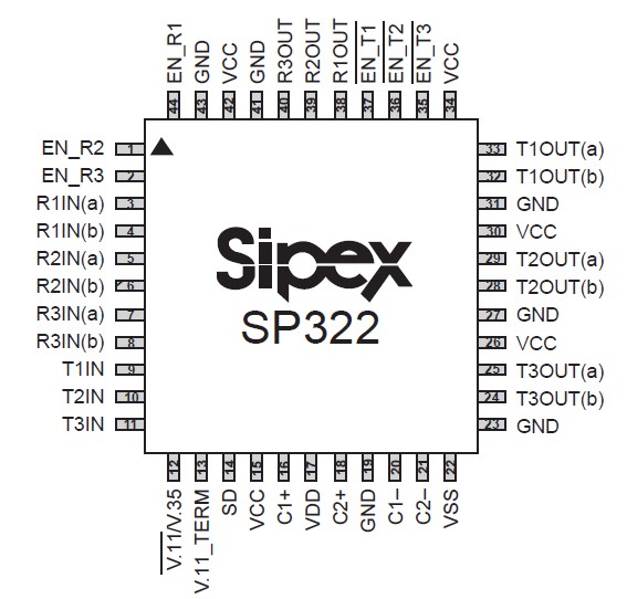
SP322: ApplicationThe SP322 is designed for serial port applications needing V.11 and V.35 transceivers. The SP322 supports a variety of physical layer protocols such as EIA-530, EIA-530A, RS-449,and V.36 ...
SeekIC Buyer Protection PLUS - newly updated for 2013!
268 Transactions
All payment methods are secure and covered by SeekIC Buyer Protection PLUS.
The SP322 is designed for serial port applications needing V.11 and V.35 transceivers. The SP322 supports a variety of physical layer protocols such as EIA-530, EIA-530A, RS-449,and V.36 where V.11 transceivers are used for clock and data signals. The termination resistors are recommended for crosstalk and reflections elimination under higher speed operation.Internal termination solves many headaches and configuration hassles with implementing V.11 and V.35. The SP322 provides a simple, lowcost solution for the clock and data lines for synchronous serial ports. The handshaking lines such as CTS, DTR, etc. can be implemented using discrete RS-422 or RS-232 transceivers,depending on the mode supported. Sipex supplies either differential (V.11) or singleended(V.28) discrete transceiver products to mate with the SP322.

| Specifications | |
| No. of Tx | 3 |
| No. of Rx | 3 |
| Data Rate (kbps) | 10000 |
| Vcc (V) | 5 |
| ESD (KV) | 2 |
| SupportedProtocols | V.11, V.35 |
| Comments | Clock/Data transceivers |
The SP322 is a programmable V.11 or V.35 transceiver IC. It contains three drivers and three receivers when selected in each mode. The selection is done by the V.11/V.35 select pin. The V.11 transceivers can typically operate at 10Mbps while adhering to the ITU V.11 specifications. The V.35 transceivers can operate up to 10Mbps while adhering to the ITU V.35 specifications.
The SP322 contains internal resistor termination for compliant V.35 operation as well as the V.11 termination on the receiver inputs for optional cable termination. Each SP322 driver contains a control pin which disables the output and places the output pins in a high impedance state. Each receiver also has a control pin which places the receiver outputs in a high impedance state. The enable pins will disconnect the internal termination network for whichever mode the SP322 is selected. For the receivers, the enable pin will place the input pins in a high impedance (approx. 15k?). This allows for convenient DTE-DCE configuration by connecting the driver outputs to the receiver inputs, thus allowing the enable pins to select the desired DTE or DCE operation.