DescriptionThe SP508CF is one member of the SP508 series.The SP508 Evaluation Board is designed to analyze the SP508 multi-protocol transceivers.The evaluation board provides access points to all of the driver and receiver I/O pins so that the user can measure electrical characteristics and wavefo...
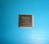
SP508CF: DescriptionThe SP508CF is one member of the SP508 series.The SP508 Evaluation Board is designed to analyze the SP508 multi-protocol transceivers.The evaluation board provides access points to all of...
SeekIC Buyer Protection PLUS - newly updated for 2013!
268 Transactions
All payment methods are secure and covered by SeekIC Buyer Protection PLUS.
The SP508CF is one member of the SP508 series.The SP508 Evaluation Board is designed to analyze the SP508 multi-protocol transceivers.The evaluation board provides access points to all of the driver and receiver I/O pins so that the user can measure electrical characteristics and waveforms of each signal.The SP508 Evaluation Board also includes a DB-25 serial port connector which is configured to a EIA-530 pinout.This allows easy connections to other DTE or DCE systems as well as network analyzers.
Features of the SP508CF are:(1)easy evaluation of SP508 multi-protocol transceiver; (2)eight (8) drivers and eight (8) receivers; (3)current mode V.35 drivers; (4)internal line or digital loopback; (5)internal transceiver termination resistors for V.11 and V.35; (6)termination network disable option; (7)fast 20Mbps differential transmission rates; (8)adheres to CTR1/CTR2 compliancy requirements; (9)PCB friendly flow-through pinout; (10)improved ESD tolerance for analog I/Os.
The absolute maximum ratings of the SP508CF can be summarized as:(1)storage temperature:-65 to 150;(2)operating temperature:-65 to 150.Connect a system clock or a signal generator with a TTL-level output and the appropriate frequency within the acceptable range of the driver under test to driver input you wish to evaluate. There is an individual enable line for each driver that can be used to tri-state the driver. Each enable line has an internal pull up or pull down insure the driver is enabled if the enable pin is not connected or floating. Set the appropriate DIP switch to the "OFF" position to enable the driver under test.The SP508 uses a 3 bit decoder to designate the protocol selected. There is also a decoder latch pin available.Table 2 and Table 3 show the decoder modes for the driver and receiver. Upon power up the latch pin needs to be in a transparent state (logic low or floating) or the SP508 will be in an unknown state. Note that D0, D1, and D2 set as logic high will put the device shutdown overriding all individual enable/disable lines and the drivers outputs and receiver inputs will tri-state.In shutdown mode the termination resistors also disconnect.