Features: Input formats
The audio decoder accepts: Dolby Digital, MPEG-1 layers I and II, MPEG-2 layer II 6-channel, PCM, CDDA data formats; MPEG2 PES streams for MPEG 2,MPEG-1, Dolby Digital, MP3, and Linear PCM (LPCM). SPDIF input data (IEC-60958 or IEC-61937 standards) is accepted if an external circuitry extracts the PCM clock from the stream.
Audio/video synchronization
Skip frame, repeat blocks and soft mute frame features can be used to synchronize audio and video data. PTS audio extraction is also supported.
Output formats
The device outputs up to 6 channels of PCM data and appropriate clocks for external digital-to-analog converters.
6 PCM data on three outputs: left/right, centre/subwoofer and left surround/right surround: DAC_PCMOUT2-0;
three clocks for the external DACs: DAC_PCMCLK, DAC_SCLK and DAC_LRCLK;
Programmable downmix enables 1, 2, 3 or 4 channel outputs. Data can be output in either I2S format or Sony format. The decoder can format output data according to IEC-60958 standard (for non compressed data: L/R channels, 16, 18, 20 and 24-bits) or IEC-61937 standard (for compressed data), for FS = 96 kHz, 48 kHz, 44.1 kHz or 32 kHz.
Sampling frequencies
Sampling frequencies (set by register AUD_SFREQ) of 96 kHz, 48 kHz, 44.1 kHz, 32 kHz and half sampling frequencies are supported. A down-sampling filter (96 kHz/48 kHz) is available.
Special modes
The decoder supports dual mode for MPEG and Dolby Digital. It includes a Dolby surround compatible downmix and a
ProLogic decoder.
A pink noise generator enables the accurate positioning of speakers for optimal surround sound setup. PCM beep tone is a special mode used for set-top box. It generates a triangular signal, of variable frequency and amplitude, on the left and right channels. In global mute mode, the decoder decodes the incoming bitstream normally but the PCM and SPDIF outputs are softmuted. This mode is used to prepare a period of decoding mode, to synchronize audio and video data without hearing the audio.
Virtual Surround
The 24-bit audio DSP cell supports TruSurround, SRS Labs?virtual technology for two-speaker playback of multichannel audio. This reduces 6 channels of either Dolby Digital (AC-3) or MPEG Multichannel audio to two channels only, providing to the user virtual multichannel sound effect. Information on how to use this feature is sent to SRS Labs Licensees only.
Trick modes
Slow-forward and fast-forward trick modes are available for compressed and non-compressed data.
Control interface
The control interface of the decoder is activated via memory mapped registers in the ST20 address space.
Pinout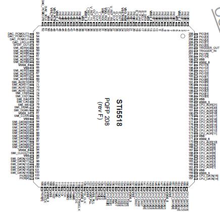 Specifications
|
Symbol |
Parameter |
Min. |
Max. |
Units |
|
VDD3_3 |
Power Supply (pads) |
-0.5 |
4 |
V |
|
VDD2_5 |
Power Supply (core) |
-0.5 |
3 |
V |
|
VDD_RGB, VDD_YCC, VDD_PLL, VDD_PCM |
Power Supply |
-0.5 |
4 |
V |
|
VI, VO |
Voltage on input and output pins |
-0.5 |
4 |
V |
|
Tstg |
Storage Temperature |
-65 |
+150 |
ºC |
|
Toper |
Ambient Operating Temperature |
0 |
+70 |
ºC |
DescriptionThere are two on-chip 3x10-bit digital-to-analog converters (triple DACs) used for video output. One provides output signals in CVBS, Y, C, and the other in RGB. The figure below shows the DAC schematic.
An external reference resistor is associated with the bandgap voltage to generate a reference current. This resistor is connected between the V_REF pin of the bandgap and a dedicated I_REF pin to achieve a higher noise immunity.
The global segmented architecture is presented in the figure below. Current-sources provide an output range of 1.45V maximum with good linearity. Sampled data are available on video outputs after 1 clock period (on the next rising clock edge)

 STi5518 Data Sheet