Features: · TrenchFET®Power MOSFETS· Ultra Low rDS(on)· Ultra Low VF Schottky· Si5853DC Pin CompatibleApplication· Buck Rectifier Switch, Buck-Boost· Synchronous Rectifier or Load· Switch For Portable DevicesPinoutSpecifications Parameter Symbol 5 secs Steady State Unit Drain-Sou...
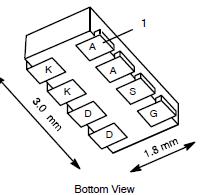
Si5856DC: Features: · TrenchFET®Power MOSFETS· Ultra Low rDS(on)· Ultra Low VF Schottky· Si5853DC Pin CompatibleApplication· Buck Rectifier Switch, Buck-Boost· Synchronous Rectifier or Load· Switch For Po...
SeekIC Buyer Protection PLUS - newly updated for 2013!
268 Transactions
All payment methods are secure and covered by SeekIC Buyer Protection PLUS.

| Parameter | Symbol | 5 secs | Steady State | Unit | |
| Drain-Source Voltage(MOSFET and Schottky) | VDS | 20 | V | ||
| Reverse Voltage (Schottky) | VKA | 20 | |||
| Gate-Source Voltage(MOSFET) | VGS | ±8 | |||
| Continuous Drain Current (TJ = 150) (MOSFET)a | TA = 25 | ID | 5.9 | 4.4 | A |
| TA = 85 | 4.2 | 3.1 | |||
| Pulsed Drain Current(MOSFET) | IDM | 20 | |||
| Continuous Source Current (MOSFET Diode Conduction)a | IS | 1.8 | 0.9 | ||
| Average Foward Current (Schottky) | IF | 1.0 | 1.0 | ||
| Pulsed Foward Current (Schottky) | IFM | 7 | |||
| Maximum Power Dissipation (MOSFET)a | TA = 25 | PD | 2.1 | 1.1 | W |
| TA = 85 | 1.1 | 0.6 | |||
| Maximum Power Dissipation (Schottky)a | TA = 25 | 1.9 | 1.1 | ||
| TA = 85 | 1.0 | 0.56 | |||
| Soldering Recommendations (Peak Temperature)b, c | 260 | ||||
| Operating Junction and Storage Temperature Range | TJ, Tstg | -55 to 150 | |||
Notes
a. Surface Mounted on 1" x 1" FR4 Board.
b. See Reliability Manual for profile. The ChipFET is a leadless package. The end of the lead terminal is exposed copper (not plated) as a result of the singulation process in manufacturing. A solder fillet at the exposed copper tip cannot be guaranteed and is not required to ensure adequate bottom side solder interconnection.
c. Rework Conditions: manual soldering with a soldering iron is not recommended for leadless components.