Features: `Display RAM : 160 (64 + 1) = 10,400 bits
`LCD drive outputs : 160 segment outputs 65 common outputs (including one common output for icon)
`RAM data direct display : Turned on when bit data in RAM = 1 Turned off when bit data in RAM = 0
`Display duty cycle : 1/2 duty during power save mode 1/35, 1/49, 1/57, or 1/65 duty during normal mode (Duty cycles in normal mode are set in software by the MPU.)
`Display modes : Normal mode ............. Full display Power save mode ....... Icon display Standby mode ............ Clock stop (all internal circuits turned off)
`MPU : 8−bit (68 / 80 series) parallel or serial interface
`Oscillator : Built−in CR oscillator (resistor and capacitor completely built−in), external clock input acceptable
`Power supply circuits : D/A converter for LCD drive power supply (temperature derating = 0.20% / °C), step−up circuit (*2 to *5), contrast control circuit
`Operating voltages : AVDD (used for analog) = DVDD to 5.5 V DVDD (used for digital) = 1.8 to 3.3 V
`LCD drive voltage : VCC = 16.5 V (max)
`CMOS process
`Low power consumption : ISS = 103 A (typ.) Conditions: AVDD = DVDD = 3.0 V, step−up circuit used (*4 mode), LCD nonloaded, Ta = 25°C, display data = all "checker pattern," no data access from MPUPinout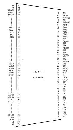 Specifications
| Item |
Symbol |
Rating |
Unit |
Remark |
| Power Supply Voltage (1) |
DVDD, AVDD |
−0.3~VSS + 7.0 |
V |
(Note 1) |
| Power Supply Voltage (2) |
(Note 2) |
−0.3~VSS + 18.0 |
V |
(Note 1), (Note 3) |
| Input Voltage (1) |
VINA |
−0.3~AVDD + 0.3 |
V |
(Note 1), (Note 4) |
| Input Voltage(2) |
VIND |
−0.3~DVDD + 0.3 |
V |
(Note 1), (Note 4) |
| Output Voltage (1) |
VOA |
−0.3~VSS + 18.0 |
V |
(Note 1) |
| Output Voltage (2) |
VOD |
−0.3~DVDD + 0.3 |
V |
(Note 1) |
| Operating Temperature |
Topr |
-20 to 75 |
°C |
|
| Storage Temperature |
Tstg |
-55 to 125 |
°C |
|
Note 1: These values are referenced to AVSS = DVDD = 0 V.
Note 2: VCC, VLC0, VLC1, VLC2, VLC3, VLC4, VLC5
Note 3: The condition VCC VLC0 VLC1 VLC2 VLC3 VLC4 VLC5 must always be met.
Note 4: The condition AVDD DVDD must always be met.
Note 5: If the device is used exceeding its absolute maximum ratings, the device may not only break down but also loose reliability and malfunction. Therefore, Toshiba recommends that for normal operation, the device be used within the range of electrical characteristics shown in the next page.
DescriptionThe T6K11 driver is designed for use in small to medium−sized dot matrix LCD panels. This driver can be interfaced to the MPU via a 4 / 8−bit (68 / 80−series) or a serial interface, and is operated asynchronously with the MPU. Since the T6K11 contains an CR circuit clock driver, it can generate the timing signals required for the LCD.
The display data can be stored in the built−in display RAM, whose cells each correspond to each dot on the dot−matrix LCD. The display data written to the RAM corresponds one for one to the LCD drive signals output by the device. Since the T6K11 has 160 outputs for the LCD drive (segment) signals that constitute display data and 65 outputs for the LCD drive (common) signals that constitute scanning signals, this single device allows you to drive an LCD panel comprised of up to 160 * 65 dots with a minimum of power requirement.
To minimize its power consumption, the T6K11 has a display change mode (power save mode) in which only a 160 * 1−dot icon can be displayed. What's more, it has variousbuilt−in analog circuits such as a D / A converter for the LCD drive power supply, a step−up circuit (*2 to *5), and a contrast control (electronic VR) circuit. All these circuits enable the LCD panel to be driven with a single power supply.
This T6K11 is under development; hence, specifications may change without notice. When you use this product, please refer to the latest technical datasheet.

 T6K11 Data Sheet


