TDA 16888

Features: `PFC Section IEC 1000-3 compliant Additional operation mode as auxiliary power supply Fast, soft switching totem pole gate drive (1 A) Dual loop control (average current and voltage sensing) Leading edge triggered pulse width modulation Peak current limitation Topologies of PFC preconver...

product image

TDA 16888 Picture
SeekIC No. : 004516005 Detail

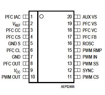
TDA 16888: Features: `PFC Section IEC 1000-3 compliant Additional operation mode as auxiliary power supply Fast, soft switching totem pole gate drive (1 A) Dual loop control (average current and voltage sensin...

floor Price/Ceiling Price

Part Number:
TDA 16888
Supply Ability:
5000

Price Break

  • Qty
  • 1~5000
  • Unit Price
  • Negotiable
  • Processing time
  • 15 Days
Total Cost: $ 0.00

SeekIC Buyer Protection PLUS - newly updated for 2013!

  • Escrow Protection.
  • Guaranteed refunds.
  • Secure payments.
  • Learn more >>

Month Sales

268 Transactions

Rating

evaluate  (4.8 stars)

Upload time: 2024/4/24

Payment Methods

All payment methods are secure and covered by SeekIC Buyer Protection PLUS.

Notice: When you place an order, your payment is made to SeekIC and not to your seller. SeekIC only pays the seller after confirming you have received your order. We will also never share your payment details with your seller.
Product Details

Description


Features:

`PFC Section
IEC 1000-3 compliant
Additional operation mode as auxiliary power supply
Fast, soft switching totem pole gate drive (1 A)
Dual loop control (average current and voltage sensing)
Leading edge triggered pulse width modulation
Peak current limitation
Topologies of PFC preconverter are boost or flyback
Continuous/discontinuous mode possible
94% maximum duty cycle
`PWM Section
Improved current mode control
Fast, soft switching totem pole gate drive (1 A)
Soft-start management
Trailing edge triggered pulse width modulation
Topologies of PWM converter are feed forward or flyback
50% maximum duty cycle to prevent transformer saturation
fPWM = fPFC


Application

Parameter
Symbol
Limit Values
Unit
 
min.
max.
VCC supply voltage VS 0.3 VZ3 V VZ3 = Zener voltage of Z3
Zener current of Z3 IZ3   50 mA  
VREF voltage VVREF 0.3 8 V VVREF < VS
ROSC voltage VROSC 0.3 8 V VROSC < VS
SYNC voltage VSYNC 0.3 8 V  
PFC FB voltage VPFC FB 0.3 8 V  
PFC IAC voltage VPFC IAC 0.3 15 V  
AUX VS voltage VAUX VS 0.3 8 V  
PFC VS voltage VPFC VS 0.3 8 V IPFC VS< 1 mA
PFC CL voltage VPFCCL 0.3 3 V  
PWM SS voltage VPWMSS 0.3 8 V VPWM SS < VVREF
PWM IN voltage VPWM IN 0.3 8 V  
PWM RMP voltage VPWMRMP 0.3 8 V VPWM RMP < VVREF
PWM CS voltage VPWM CS
0.3 3 V  
PFC VC voltage VPFC VC 0.3 8 V  
PFC VC current IPFC VC 20 20 mA  
PFC CS current IPFC CS 5 5 mA  
GND S current IGNDS 5 5 mA  
PFC CC voltage VPFCCC 0.3 8 V  
PFC CC current IPFCCC 20 20 mA  
PFC/PWM OUT DC current IOUT 100 100 mA  
PFC/PWM OUT peakclamping current IOUT   200 mA VOUT = High
PFC/PWM OUT peak
clamping current
IOUT 500     VOUT = Low
Junction temperature Tj 40 150 °C  
Storage temperature Ts 65 150 °C  
Thermal resistance RthSA   60 K/W P-DIP-20-5
Thermal resistance RthJA   70 K/W P-DSO-20-1

Note: Absolute maximum ratings are defined as ratings, which when being exceeded may lead to destruction of the integrated circuit. To avoid destruction make sure, that for any pin except for pins PFC OUT and PWM OUT the currents caused by transient processes stay well below 100 mA. For the same reason make sure, that any capacitor that will be connected to pin 9 (VCC) is discharged before assembling the application circuit. In order to characterize the gate driver's output performance Figure 14, Figure 15, Figure 16 and Figure 17 are provided, instead of referring just to a single parameter like the maximum gate charge or the maximum output energy.


Pinout

  Connection Diagram


Customers Who Bought This Item Also Bought

Margin,quality,low-cost products with low minimum orders. Secure your online payments with SeekIC Buyer Protection.
Soldering, Desoldering, Rework Products
Motors, Solenoids, Driver Boards/Modules
Isolators
Fans, Thermal Management
Transformers
View more