Want to post a buying lead? If you are not a member yet, please select the specific/related part number first and then fill the quantity and your contact details in the "Request for Quotation Form" on the left, and then click "Send RFQ".Your buying lead can then be posted, and the reliable suppliers will quote via our online message system or other channels soon.
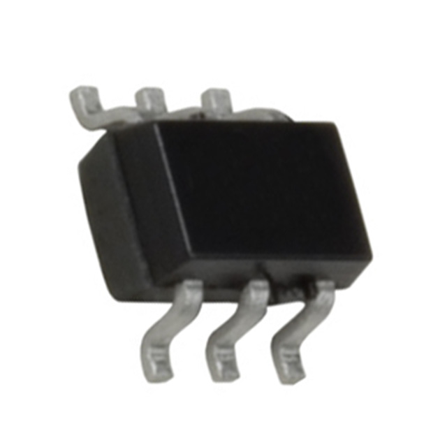
These dual P-Channel logic level enhancement mode MOSFET are produced using Fairchild Semiconductor's advanced PowerTrench process that has been especially tailored to minimize on-state resistance. This device has been designed especially for low voltage applications as a replacement for bipolar digital transistors and small signal MOSFETS.
FDG6318P Maximum Ratings
Symbol
Parameter
Ratings
Units
VDSS
Drain-Source Voltage
-20
V
VGS
Gate-Source Voltage
±12
V
ID
Drain Current Continuous (Note 1) Pulsed
-0.5
A
-1.8
PD
Power Dissipation for Single Operation (Note 1)
0.3
W
TJ, TSTG
Operating and Storage Temperature
-55 to 175
Notes: 1. RJA is the sum of the junction-to-case and case-to-ambient thermal resistance where the case thermal reference is defined as the solder mounting surface of the drain pins. RJC is guaranteed by design while RJA is determined by the user's board design. RJA = 415°C/W when mounted on a minimum pad .
FDG6318P Features
• 0.5 A, 20 V. RDS(ON) = 780 mΩ @ VGS = 4.5 V RDS(ON) = 1200 mΩ @ VGS = 2.5 V • Very low level gate drive requirements allowing direct operation in 3V circuits (VGS(th) < 1.5V). • Compact industry standard SC70-6 surface mount package
FDG6318P Typical Application
• Battery management
FDG6318PZ Parameters
Technical/Catalog Information
FDG6318PZ
Vendor
Fairchild Semiconductor
Category
Discrete Semiconductor Products
Mounting Type
Surface Mount
FET Polarity
2 P-Channel (Dual)
Drain to Source Voltage (Vdss)
20V
Current - Continuous Drain (Id) @ 25° C
500mA
Rds On (Max) @ Id, Vgs
780 mOhm @ 500mA, 4.5V
Input Capacitance (Ciss) @ Vds
85.4pF @ 10V
Power - Max
300mW
Packaging
Tape & Reel (TR)
Gate Charge (Qg) @ Vgs
1.62nC @ 4.5V
Package / Case
SC-70-6, SC-88, SOT-323-6, SOT-363
FET Feature
Logic Level Gate
Lead Free Status
Lead Free
RoHS Status
RoHS Compliant
Other Names
FDG6318PZ FDG6318PZ
FDG6318PZ General Description
These dual P-Channel logic level enhancement mode MOSFET are produced using Fairchild Semiconductor's especially tailored to minimize on-state resistance. This device has been designed especially for bipolar digital transistors and small signal MOSFETS
Electrostatic Discharge Rating MIL-STD-883D Human Body Model ( 100pF / 1500Ω )
FDG6318PZ Features
• -0.5A, -20V. rDS(ON) = 780mΩ (Max)@ VGS = -4.5 V rDS(ON) = 1200mΩ (Max) @ VGS = -2.5 V • Very low level gate drive requirements allowing direct operation in 3V circuits (VGS(TH) < 1.5V). • Gate-Source Zener for ESD ruggedness (>1.4kV Human Body Model). • Compact industry standard SC-70-6 surface mount package.
FDG6318PZ Connection Diagram
FDG6320C Parameters
Technical/Catalog Information
FDG6320C
Vendor
Fairchild Semiconductor
Category
Discrete Semiconductor Products
Mounting Type
Surface Mount
FET Polarity
N and P-Channel
Drain to Source Voltage (Vdss)
25V
Current - Continuous Drain (Id) @ 25° C
220mA, 140mA
Rds On (Max) @ Id, Vgs
4 Ohm @ 220mA, 4.5V
Input Capacitance (Ciss) @ Vds
9.5pF @ 10V
Power - Max
300mW
Packaging
Tape & Reel (TR)
Gate Charge (Qg) @ Vgs
0.4nC @ 4.5V
Package / Case
SC-70-6, SC-88, SOT-323-6, SOT-363
FET Feature
Logic Level Gate
Lead Free Status
Lead Free
RoHS Status
RoHS Compliant
Other Names
FDG6320C FDG6320C
FDG6320C General Description
These dual N & P-Channel logic level enhancement mode field effect transistors are produced using Fairchild's proprietary, high cell density, DMOS technology. This very high density process is especially tailored to minimize on-state resistance. This device has been designed especially for low voltage applications as a replacement for bipolar digital transistors and small signal MOSFETS. Since bias resistors are not required, this dual digital FET can replace several different digital transistors, with different bias resistor values.
FDG6320C Maximum Ratings
Symbol
Parameter
N-Channel
P-Channel
Units
VDSS VGSS
Drain-Source Voltage Gate-Source Voltage
25 8 0.22 0.65
-25 -8 -0.14 -0.4
V V A
W
°C kV
ID
Drain Current - Continuous - Pulsed
PD
Power Dissipation for Single Operation
(Note 1)
0.3 -55 to 150 6
TJ,TSTG ESD
Operating and Storage Temperature Ranger Electrostatic Discharge Rating MIL-STD-883D Human Body Model (100pf / 1500 Ohm)
FDG6320C Features
·N-Ch 0.22 A, 25 V, RDS(ON) = 4.0 W @ VGS= 4.5 V, RDS(ON) = 5.0 W @ VGS= 2.7 V. ·P-Ch -0.14 A, -25V, RDS(ON) = 10 W @ VGS= -4.5V, RDS(ON) = 13 W @ VGS= -2.7V. ·Very small package outline SC70-6. ·Very low level gate drive requirements allowing direct operation in 3 V circuits (VGS(th) < 1.5 V). ·Gate-Source Zener for ESD ruggedness (>6kV Human Body Model).