A/D-D/A Converter Circuit
TWO_8_BIT_DACS_MAKE_A_12_BIT_DAC
Published:2009/7/1 21:25:00 Author:May | From:SeekIC
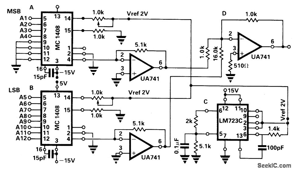
Two MC1408-8-bit D/A converters, A and B in the circuit diagram, are used. The four least significant bits of A are tied to zero. The four most significant bits of the 12-bit data are connected to the remaining four input pins. The eight least significant bits of the 12-bit data are connected to the eight input pins of B. The four most significant bits of the 12-bit data together have a weight of 16 relative to the remaining eight bits. Hence, the output from B is reduced by a factor of 16 and summed with the output from A using the summing op-amp configuration D. Voltage regulator chip, LM7236, is used to provide an accurate reference voltage, 2 V, for the MC1408. The full-scale voltage of the converter is 1/16 x 9.9609 + 1 x (9.375) or 9.9976 V. The step size of the converter is 2.4 mV.
Reprinted Url Of This Article:
http://www.seekic.com/circuit_diagram/A-D_D-A_Converter_Circuit/TWO_8_BIT_DACS_MAKE_A_12_BIT_DAC.html
Print this Page | Comments | Reading(3)

Article Categories
power supply circuit
Amplifier Circuit
Basic Circuit
LED and Light Circuit
Sensor Circuit
Signal Processing
Electrical Equipment Circuit
Control Circuit
Remote Control Circuit
A/D-D/A Converter Circuit
Audio Circuit
Measuring and Test Circuit
Communication Circuit
Computer-Related Circuit
555 Circuit
Automotive Circuit
Repairing Circuit
Code: