
Repairing Circuit
Index
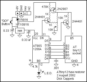
ATtiny12 fuse restorer
Published:2013/1/22 21:01:00 Author:muriel | Keyword: ATtiny12, fuse restorer
View full Circuit Diagram | Comments | Reading(3971)
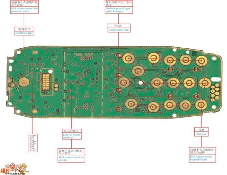
Nokia 3300 mobile fault repairing material object color drawing
Published:2011/10/17 1:05:00 Author:Ecco | Keyword: Nokia , mobile fault repairing , material object, color drawing
View full Circuit Diagram | Comments | Reading(4820)
Applied circuit diagram of nrf401 wireles receiving and dispatching chip
Published:2011/9/7 6:52:00 Author:Vicky | Keyword: nrf401 wireles receiving and dispatching chip
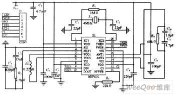
In this design, wireless radio frequency adopts nrf401 receiving and dispatching chips launched by a Norway company called Nordic. The chip uses 433 mhz ism frequent range. It is the real monolithic uhf wireless receiving and dispatching chip. The 20 pins chip contains high frequency transmitting, high frequency receiving, pll synthetic, fsk modulation, multi-channel chang-over and so on. It is a wireless data transmitting product of the highest integrated level at present. The wireless radio frequency module adopts differential circuit loop-antenna. The load impedance of the antenna end is 380ω. The circuit principle is shown in the above picture. The parameters of the exterior components are listed in the picture, among which, j1 is the interface of the wireless radio frequency module and control module. (View)
View full Circuit Diagram | Comments | Reading(3126)
Wide-range Digital Capacity Measuring Instrument Circuit (NE555, CD4017, MC14553B)
Published:2011/8/10 8:17:00 Author:Felicity | Keyword: Wide-range, Digital, Capacity Measuring Instrument
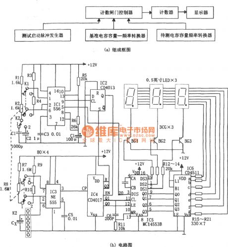
The pulser is the multivibrator consists of IC1(556) and R1,R2,C1(R3,R4,C2), and the oscillation frequency is 1.44/(R1+2R2)C1,or f2=1.44/(R3+2R4)C2. The advancing edge of the pulse output by pin 9 make the output terminal of D flip-flop IC2(CD4013) generate low voltage that put on the enable terminal (EN terminal) of the counter IC4(CD4071) to make it count. The pulse output by pin 5 control the DIS terminal of the 3 bit BCD counting circuit IC5 (MC14553B) The test capacitor capacity-frequency transform circuit consists of R7, R8, and IC3 (555) and the test capacitor Cx. It transforms the capacity of Cx into oscillation pulse pending to test as the counting clock onto IC4. (View)
View full Circuit Diagram | Comments | Reading(5131)
Qisheng AV-737 Power Amplifier Complicated Troubleshooting Two Examples Circuits
Published:2011/8/2 21:46:00 Author:Robert | Keyword: Qisheng, Power Amplifier, Complicated, Troubleshooting, Two, Examples
Example 1: the error symptom. A Qisheng AV-737 amplifier is combined with VCD. When it connects the signal wire and plug in the power, the amplifier would enter the standby mode. If the user opens the VCD power firstly and thenopens the amplifier, the amplifier's all functions would be disabled (include remote-control function). When it occurs the crash failures, at this time pressing the AV-737's power plug solely, and plugging in after some seconds, then it would start normally. If each time openning the AV-737 power amplifier power and then openning VCD, it would not have the error above.Analysis and maintenance. When it occurs the faults, the standby power supply is tested to be normal, the CPU1997(or 9800)'s pin 64 and pin 46's 5V power is also tested to be normal, the pin 32 and pin 44 (ground port) are normally connected to the ground. Pressing the power switch button, the CPU's pin 28 (power) control output port has no variety. The AV-737's power switch mode is touch-button control switch. When it is connected, the CPU would receive the starting command and its pin 28 would output high voltage level. Then the control the relay to be closed to make the whole device's power connected. (View)
View full Circuit Diagram | Comments | Reading(6691)
Funai VIP-3000HCMKIII Type Videoplayer Audio Squelch Control Circuit Working Principle And Repairing Circuit
Published:2011/8/6 19:36:00 Author:Robert | Keyword: Funai, Videoplayer, Audio, Squelch, Control, Working, Principle, Repairing
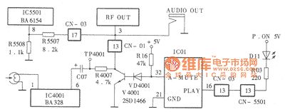
The Funai VIP-3000HCMKIII type videoplayer audio squelch control circuit is simple, but it has a high fault rate. This arctical intruduces this audio squelch control circuit's working principle and common faults' repairing methdod.Working Principle.This device's audio squelch control circuit is shown in the picture. It is made up of squelch control transistor V4001, VD4001, R16 and system control microprocessor IC01 (A.MUTE) and so on. Its working principle is intruduced here. When inserting a tape and pressing the replay key, the system control microprocessor IC01's pin would output low voltage level. Then the squelch control transistor V4001 is not conducted. The audio magnetic head picks the audio signal from the tape and then output from pin 6 through the IC4001 (BA328)'a pre-equilibrium and amplification. (View)
View full Circuit Diagram | Comments | Reading(2735)
Hangchan HENTR Brand Constant Voltage Power Amplifier No Output Special Fault Repairing Circuit
Published:2011/8/6 8:53:00 Author:Robert | Keyword: Hangchan, HENTR, Constant, Voltage, Power Amplifier, Output, Special, Fault, Repairing
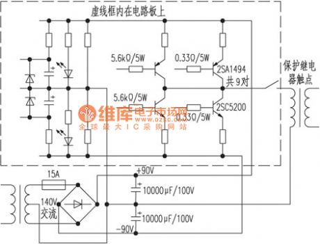
When checking at starting, it finds one of the two 10000uF/100V power filter capacitors is rupturing. So it could only remove the ruptured capacitor and carefully wipe the electrolyte on the circuit board. Then checking the power tube and it is not found the sign of short circuit. At last it replaces a new 10000uF/100V filter capacitor and internal-device 15A fuse. Then trying the device it is all normal. After some days it is found that when starting the relay sometimes could be connected but sometimes it couldn't and also has the alarm sound. It also finds the following law. If firstly starting after shutting off for a long time, the relay could always be connected. And if starting after shutting off for not a long time, the relay could be sometimes connected and sometimes not connected. (View)
View full Circuit Diagram | Comments | Reading(3129)
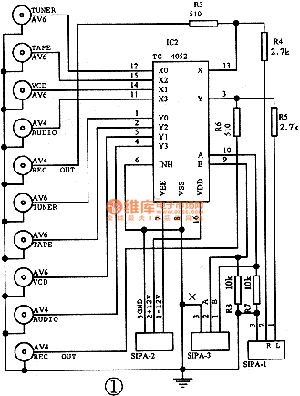
Jianlong AV320 Power Amplifier Volume Automatically Increasing Repairing Circuit
Published:2011/8/4 10:02:00 Author:Robert | Keyword: Jianlong, Power Amplifier, Volume, Automatically, Increasing, Repairing
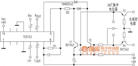
Each time it has set the volume at the starting time of the device, the volume would be increasing automatically and slowly until the maximum value. This device's volume control IC's model name is erased, and the volume could be remote controlled and also be controlled by hand. To narrow the repairing faults's range, it could firstly pluck the connection plugin to the remote-control circuit and try the device. If the fault still remains, it proves that the fault is not in the remote-control circuit, and it is in the part of electronic volume control circuit.The electronic volume control circuit TC9153's function pin is the same with it, which is shown in the picture. The signal inputs from pin 5 and pin 12. The pin 2, pin 3, pin 14, pin 15 are connected with 4558 for buffering and amplification. And the signal outputs from pin 6 and pin 11. It uses the pin 9 and pin 10's low voltage level pulse signal to achieve the control of the volume's increasing and decreasing. (View)
View full Circuit Diagram | Comments | Reading(3707)
Aileite ESR-200 Type Satellite Receiver Switch Power Troubleshooting Circuit
Published:2011/8/4 21:24:00 Author:Robert | Keyword: Aileite, Satellite, Receiver, Switch, Power, Troubleshooting
Fault 1: Starting without any instructions.If pressing the power switch, it could hear the switch transformer's normal pulses sound. By testing the output ports' voltage of each group, it is found that they are all just a half of the normal working voltage. By adjusting the VR and testing the IC2's R port's voltage, it could vary between 0.9~1.5V. The the output port K has corresponding variation. But it could achieve the normal value. The IC2's external elements are tested to be normal. Then replace a new IC2, the fault is eliminated. Testing the IC2's R port's voltage again, its result is 2.5V. The K port is 11.3V. By adjusting VR1, The IC2's R port's voltage could vary between 2.1V and 3V, also the output port's voltage has the corresponding variation. (View)
View full Circuit Diagram | Comments | Reading(4670)
Shenzhou ST-9900 Type Satellite Receiver Switch Power Repairing Circuit
Published:2011/8/5 0:14:00 Author:Robert | Keyword: Shenzhou, Satellite, Receiver, Switch, Power, Repairing

Fault 1: Starting without any indication on receiver's panel.The faults analysis and processing. Openning the case, according to the experiences it is firstly to test the power's filter capacitor's two ports (47uF/450V). And there is no voltage indication. It means the power are working without rectifier. Using the multimeter resistance stage to test the current-limiting resistor (6R2/5W), the result is infinity. By analysis, the reason caused the current-limiting resistor damaged is just that the filter capacitor, power regulator tube and other elements are broken. Testing the filter capacitor (47uF/450V), it is found that its upside part has been bulging. Then removing this capacitor to test, it is found to have breakdown. Replacing the filter capacitor and the current-limiting resistor, the receiver panel has the normal indication and the fault is soved. (View)
View full Circuit Diagram | Comments | Reading(3600)
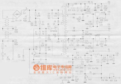
Fushida FR960 Satellite Receiver Repairing Circuit
Published:2011/8/5 20:07:00 Author:Robert | Keyword: Fushida, Satellite, Receiver, Repairing
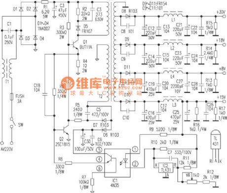
Firstly visually checking the power board, it finds the fuse is burned to be black. The IC2 4N35 (over-voltage protector), IC3 4N35 (voltage regulator control), Q1 C2060, Q5, C1815 (here it is different from the Wanlida device, Q5 is connected between the IC2 and SCR QBT1690 for over-voltage conversion) are all rupturing. Checking in the circuit it is found that the AV input anti-jamming inductive choke L1, 220V rectifier D1, D2, current limiting resistor R7, C4, switching tube Q3 BU508A, R8, R13, D14 3.6V voltage regulator, C9, Q6 SCR BT1690 are damaged. In the back of the power board there are many copper wires are burned to be black and dropping. The printed board are beyond recognition. In the bottom of the power shield iron box it also has the signs of electric shock. (View)
View full Circuit Diagram | Comments | Reading(2767)
Jingtaike 1288, 628 Satellite Receiver CPU Fault Emergency Maintenance Circuit
Published:2011/8/4 19:58:00 Author:Robert | Keyword: Jingtaike, Satellite, Receiver, CPU, Fault, Emergency, Maintenance
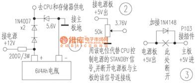
1.Using a 6V 4Ah maintenance-free battery to supply the 5V voltage for CPU and memory (shown in the picture) through two 1N4007 diodes for voltage step-down. The supply current is only 10mA, which would let the CPU and memory to work in a long time and keep the predetermined mode permanently. So that when starting again the CPU would not refuse the power supply.2.The power board +5V power supply voltage should be in series with a low-voltage-drop diode (such as 1N4148) and then it is connected to the main board. Otherwise when starting again, the power's +12V and Vcc voltage would be not normal. (View)
View full Circuit Diagram | Comments | Reading(2183)
Gaosineibeier GSR-2001E Digital Satellite Receiver Switch Power Principle And Repairing Circuit
Published:2011/8/6 19:49:00 Author:Robert | Keyword: Gaosineibeier, Digital, Satellite, Receiver, Switch, Power, Principle, Repairing
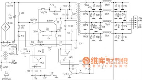
1.Switch power working principle.(1)The power input part.The L5, L6 and C23, C1 are make up the dual common-mode low-pass filter network. Its function is to inhibit the EMI from the power network. Also it could inhibit the EMI from the switch power itself to ensure the power network is not polluted. This combination has a good inhibiting function for many kinds of high-frequency interfering signal. The D1~D4 and C2 are make up the bridge rectifier filter circuit. The TH1 in the picture is a thermistor element with negative temperature coefficient. Its feature is that its resistance value would be large when the temperature is low, and its resistance value is low when the temperature is high. (View)
View full Circuit Diagram | Comments | Reading(4011)
Banqiu HD-72 Type High-Temperature Disinfection Cabinet Principle And Maintenance Circuit
Published:2011/8/4 3:12:00 Author:Robert | Keyword: Banqiu, High-Temperature, Disinfection, Cabinet, Principle, Maintenance

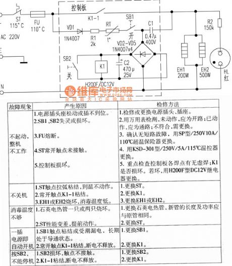
The Banqiu HD-72 type high-temperature disinfection cabinet uses remote infrared high-temperature disinfection. It has many advantages such as fast warming, thorough disinfection, automatical temperature control, safe to use, and so on.1.The principle of the circuit.The principle circuit which is drawn based on the physical circuit is shown in the picture. The whole circuit is made up of two parts which are control circuit (in the border of the picture) and heating and disinfection circuit.When it is connected to the power, by pressing the disinfection button SB1, the 220V AC power would be added on the VD2~VD5 bridge rectifier and C2 filter through the disinfection temperture controller ST, over-temperature fuse FU, diode VD1, current-limiting resistor R1, thermistor RT (PTC). This would make the relay K1 be closed and the normally open contactor K1-1 would also be closed. (View)
View full Circuit Diagram | Comments | Reading(2168)
Jintaike KT-D8302 Digital Satellite Receiver Power Common Fault Repairing Circuit
Published:2011/8/6 20:01:00 Author:Robert | Keyword: Jintaike, Digital, Satellite, Receiver, Power, Common, Fault, Repairing
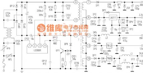
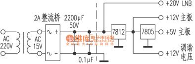
The Jintaike KT-D8302 digital satellite receiver switch power uses the 4-pin integrated module IL0380R to complete the oscillation and output. It looks like a plastic-package power tube. By taking the IL0380R as the key, the power circuit structure is very simple. It has few elements but its performance is good and it has low power consumption. If working continuous for more than 10 hours, its case upside cover has just tepidity.
This device has a large number in the society, however its repairing material is lacking. So here it has drawn the power principle circuit for reference according to the practical device, which is shown in the picture. (View)
View full Circuit Diagram | Comments | Reading(5583)
Kangbao Brand SDX-061B Type Disinfection Cabinet Circuit And Repairing Circuit
Published:2011/8/6 9:29:00 Author:Robert | Keyword: Kangbao, Disinfection, Cabinet, Repairing
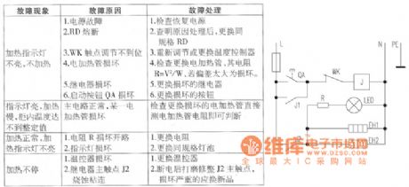
1.The circuit.
The 220V commercial power phase wire L is connected to the power button TQ through the temperature fuse RD. By pressing QA, the commercial power would be added into the relay J's coil through the dual-metal type temperature controller WR's normally closed contactor. And then the relay J would be conected, its normally open contactor J1 is also conducted and self-keeping to supply power for the relay coil. At the same time the contactor J2 is conducted to supply power for the electrical heater tube EH1, EH2. And the heating indication lamp LED is lighting which shows the disinfection cabinet is heating. The resistor R in the circuit is in series with the heating indication lamp which has the function of current limiting. The adjustable temperature controller WK make the temperature in disinfection cabinet meet the disinfection requirements. Its weakness is the operating temperature's error is some bigger. The electrical heater tube EH1, EH2's power is about 300W which is separately installed in the bottom and back in the cabinet. (View)
View full Circuit Diagram | Comments | Reading(2061)
Keling ZTP-63A Type Dual Function Disinfector Cabinet Principle And Repairing Circuit
Published:2011/8/3 9:11:00 Author:Robert | Keyword: Keling, Dual, Function, Disinfector Cabinet, Principle, Repairing
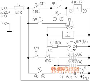
The Keling ZTP-63A type dual function tableware disinfector cabinet is dual door and dual room structure. It has many advantages such as thorough disinfection, no pollution, sage and stable, easy to use, and so on. This artical intruduces this disinfector cabinet's working principle and common faults' repairing methods for repairing reference.The working principle is intruduced below.This disinfector cabinet's circuit is drawn and shown in the picture. The full circuit is made up of three parts which are high-temperature disinfector circuit, temperature-keeping circuit and ozone disinfector circuit. In the high-temperature disinfector circuit, when it is connected to the power and the user presses the disinfector switch SB1, the relay K would get electricity and become closed. And the normally open contactor K1, K2 are closed to be connected. Then the working indication lamp (red) HL1 would light. (View)
View full Circuit Diagram | Comments | Reading(1970)
Two Kinds Of Heat Preservation Type Automatic Electric Pressure Cooker Principle And Repairing Circuit
Published:2011/7/29 6:40:00 Author:Robert | Keyword: Heat Preservation, Automatic, Electric, Pressure Cooker, Principle, Repairing
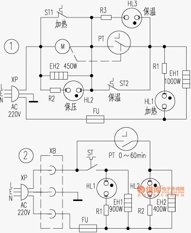
The picture shows the two kinds of heat preservation type automatic electric pressure cooker principle and repairing circuit.
1.Yongxing brand DYB50-100 type electric pressure cooker.(1)The principle of the circuit.The circuit is shown in picture 1. When it connects the power supply, clockwise rotating the timer (electric type) PT to an adequate pressure-keeping stage, and the PT contactor would be closed. So the 220V AC power would be added on the main heating loop circuit which is composed of heating temperature control device ST1, heat preservation temperature control device ST2, main heater EH1, over-heat fuse FU and so on. When the heating indication lamp HL1 is bright, the EH1 would heat and the temperature in the cooker would increase. When it gets to working pressure 85kPa, ST2, ST1 would be disconnected separately to disconnect the main heating loop circuit's power source. The HL1 would be off and the EH1 would stop heating. At this time the pressure-keeping loop circuit, which is composed of pressure-keeping heating device EH2, PT, EH1 and FU, would heat. (View)
View full Circuit Diagram | Comments | Reading(3838)
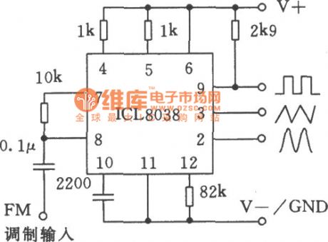
Single precision function generator ICL8038 application circuit
Published:2011/7/23 9:27:00 Author:John | Keyword: Single precision function generator, application circuit
View full Circuit Diagram | Comments | Reading(5230)
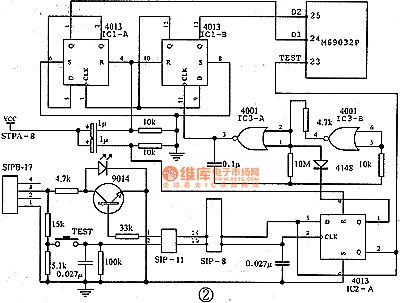
JD-6 Type Electric Motor Synthesized Protector Principle And Troubleshooting Circuit
Published:2011/7/25 8:00:00 Author:Robert | Keyword: Electric Motor, Synthesized, Protector, Principle, Troubleshooting
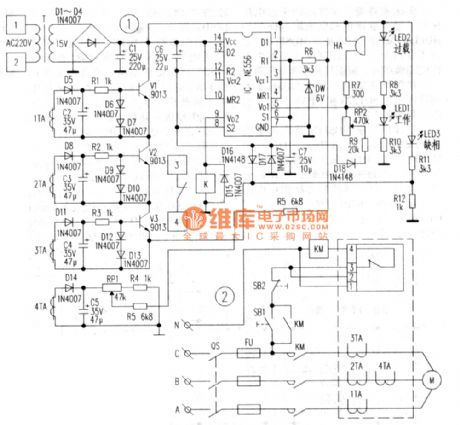
The JD-6 type electric motor synthesized protector's electrical principle schematic is shown in picture 1 and the assorted wiring with the electric motor is shown in picture 2. In picture 1 the transformer T's secondary side's 15V voltage would be send to the diodes bridge rectifier (D1~D4) and the capacitor C1 for filter. Then it would get about 15V DC voltage which would be the working voltage for the protector. The dual-time-base circuit (NE556) is the main control chip. When the motor is running the current transformer 1TA and 3TA, which are in series with the electric motor's main loop circuit, would be used to detect the motor's running current. After the half-wave rectifier in D5 and filter in C2 and currrnt limiting in R1, the 1TA's secondary side's current signal would make the triode V1 in open mode. As the same way the 2TA, 3TA's current signal would make the triode V2 and V3 in open mode separately. (View)
View full Circuit Diagram | Comments | Reading(3495)
| Pages:1/2 12 |
Circuit Categories
power supply circuit
Amplifier Circuit
Basic Circuit
LED and Light Circuit
Sensor Circuit
Signal Processing
Electrical Equipment Circuit
Control Circuit
Remote Control Circuit
A/D-D/A Converter Circuit
Audio Circuit
Measuring and Test Circuit
Communication Circuit
Computer-Related Circuit
555 Circuit
Automotive Circuit
Repairing Circuit