
Repairing Circuit
Index 2
M9900MC Camera Self-Diagnosis Repairing Status Mode Circuit
Published:2011/7/26 1:54:00 Author:Robert | Keyword: Camera, Self-Diagnosis, Repairing, Status, Mode
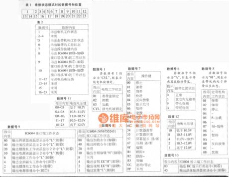
1.Repairing status mode.When the machine is in the repairing status mode, the TV sets and viewfinders' screen would display the data of the random access memory (RAM). The table 1 lists the RAM data's reading imformation and all the data is in hexadecimal mode for displaying.2.Data details in repairing status mode.When pressing the start/stop switch and the memory switch at the same time, after the power switch is connected, the TV sets' screen could display the detail information of No.1 to No.23 which is listed in table 2. And part of the data number's indicating imformation is listed after the list's contents.
The picture shows the M9900MC camera self-diagnosis repairing status mode circuit. (View)
View full Circuit Diagram | Comments | Reading(1378)
Xinke 5300A Power Amplifier Front And Central Sound-Channel Silent Repairing Circuit
Published:2011/7/24 10:07:00 Author:Robert | Keyword: Xinke, 5300A, Power Amplifier, Sound-Channel, Silent, Repairing
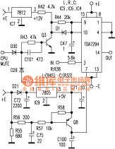
This device is a universal AV power amplifier certified by Dolby. The device's all kinds of functions and operation display is managed by a CPU (UPD78042). The selected audio signal would be send to NJW1103 for decoding after the buffer, and it would output L, R, C S four channel signals. The first two signals would be send separately to a single-chip integrated power amplifier TDA7294 for amplification after the Dolby/direct selection, balance, volume control, pre-amplification (LM833). However the central and the surround channel signals would be amplified and volume controlled directly by the LM833 and then are send to the end integrated power amplifier for amplification (C is TDA7294 and S is TDA7265). Also when starting the CPU's MUTE port will send the squelch signal and then do the squelch for each TDA7294 and TDA7265 through the squelch circuit. (View)
View full Circuit Diagram | Comments | Reading(1300)
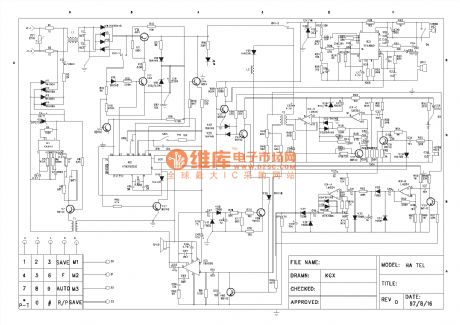
Telephone repairing reference circuit
Published:2011/6/30 21:51:00 Author:zj | Keyword: Telephone, repairing
View full Circuit Diagram | Comments | Reading(1825)
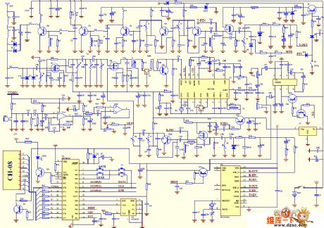
interphone circuit
Published:2011/5/17 5:13:00 Author:chopper | Keyword: interphone
View full Circuit Diagram | Comments | Reading(2771)
Motherboard maintenance drawing board - the trigger circuit
Published:2011/4/26 3:29:00 Author:Ecco | Keyword: Motherboard , maintenance, drawing board, trigger circuit

View full Circuit Diagram | Comments | Reading(1991)
The circuit diagram of instrument headers moving coil disconnection repair
Published:2011/4/21 6:01:00 Author:Crystal Liu | Keyword: instrument headers moving coil disconnection repair , circuit diagram
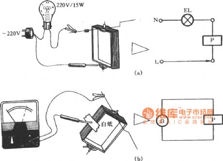
Instrument headers moving coil disconnection repair circuit. (View)
View full Circuit Diagram | Comments | Reading(1576)
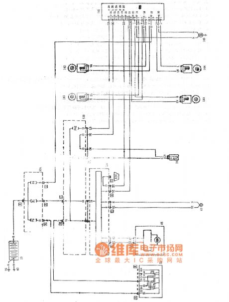
Paliao ABS circuit
Published:2011/4/20 2:44:00 Author:Jessie | Keyword: ABS
View full Circuit Diagram | Comments | Reading(1012)
Temperature compensation circuit of high-precision pressure signal conditioner MAX1457
Published:2011/3/23 19:56:00 Author:may | Keyword: Temperature compensation, pressure signal conditioner
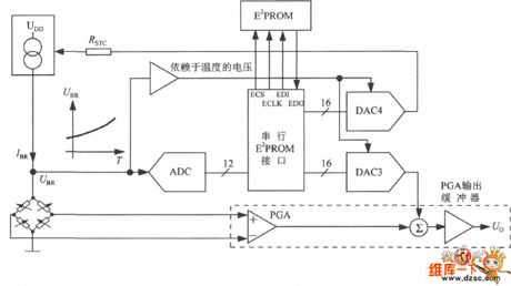
Temperature compensation circuit of high-precision pressure signal conditioner MAX1457 is shown in the following diagram:
(View)
View full Circuit Diagram | Comments | Reading(1180)
| Pages:2/2 12 |
Circuit Categories
power supply circuit
Amplifier Circuit
Basic Circuit
LED and Light Circuit
Sensor Circuit
Signal Processing
Electrical Equipment Circuit
Control Circuit
Remote Control Circuit
A/D-D/A Converter Circuit
Audio Circuit
Measuring and Test Circuit
Communication Circuit
Computer-Related Circuit
555 Circuit
Automotive Circuit
Repairing Circuit