Amplifier Circuit
Automatic gain control amplifier circuit diagram
Published:2011/7/21 1:23:00 Author:Ecco | Keyword: Automatic , gain control amplifier | From:SeekIC


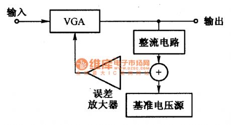
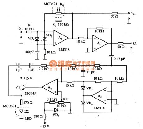
Figure 1 is automatic gain control amplifier. Figure 1 (a) is the block diagram of automatic gain control amplifier which is composed of the variable gain amplifier VGA, rectifier circuit, reference voltage source and error amplifier. Figure 1 (b) is the actual circuit, A1 may constitute VGA amplifier, of which the gain depends on the ratio of resistance value, that is the RG of the optical coupler, and the maximum gain is 15 times which is decided by the ratio of R2 and R1, and the minimum gain is determined by the minimum value of RG.
Reprinted Url Of This Article:
http://www.seekic.com/circuit_diagram/Amplifier_Circuit/Automatic_gain_control_amplifier_circuit_diagram.html
Print this Page | Comments | Reading(3)

Article Categories
power supply circuit
Amplifier Circuit
Basic Circuit
LED and Light Circuit
Sensor Circuit
Signal Processing
Electrical Equipment Circuit
Control Circuit
Remote Control Circuit
A/D-D/A Converter Circuit
Audio Circuit
Measuring and Test Circuit
Communication Circuit
Computer-Related Circuit
555 Circuit
Automotive Circuit
Repairing Circuit
Code: