Amplifier Circuit
Controlled by single chip DC brushless motor driver and interface circuit
Published:2011/7/8 2:42:00 Author:Fiona | Keyword: Controlled by single chip, DC brushless motor, driver and interface | From:SeekIC

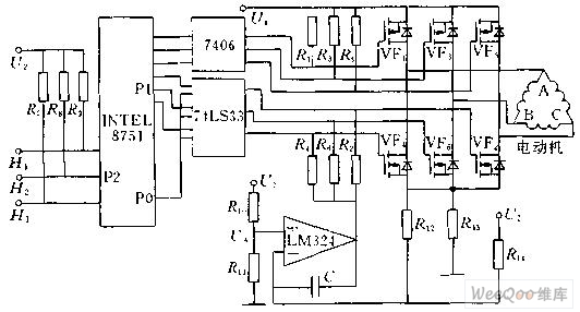
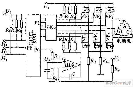
Figure 1 shows the functional block diagram of using 8751 single chip to control the brushless DC motor.8751's P1 is connected with the 7406 inverter control to control the brushless DC motor commutation,P2 is used for measuring the signal H1, H2, H3 from position sensor,P0 externally connects a digital to analog converter.According to the commutation of stator windings, first it needs to find the state of three rotor magnet position sensor signals H1,H2,H3 and the relationship between 6 power tubes,then it puts the information in tabular form to the single-chip's EEPROM.
Reprinted Url Of This Article:
http://www.seekic.com/circuit_diagram/Amplifier_Circuit/Controlled_by_single_chip_DC_brushless_motor_driver_and_interface_circuit.html
Print this Page | Comments | Reading(3)

Article Categories
power supply circuit
Amplifier Circuit
Basic Circuit
LED and Light Circuit
Sensor Circuit
Signal Processing
Electrical Equipment Circuit
Control Circuit
Remote Control Circuit
A/D-D/A Converter Circuit
Audio Circuit
Measuring and Test Circuit
Communication Circuit
Computer-Related Circuit
555 Circuit
Automotive Circuit
Repairing Circuit
Code: