Amplifier Circuit
Driver Circuit of Bridge Sensor
Published:2011/5/2 2:25:00 Author:Felicity | Keyword: Driver Circuit of Bridge Sensor, | From:SeekIC

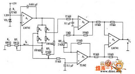
The picture shows the driver circuit of bridge sensor. We can see that in this circuit A1 is the constant current output circuit where the constent value is determined by UZ(the steady voltage of VD1) and (R(RP1)+R2). It provides the patialvalue ofconstant currentto the bridge sensor(the bridge circuit consisting of RA-RD). The amplifier which consisting of A2-A4 can magnify the signals which was outputed by seneors to the level needed.
Reprinted Url Of This Article:
http://www.seekic.com/circuit_diagram/Amplifier_Circuit/Driver_Circuit_of_Bridge_Sensor.html
Print this Page | Comments | Reading(3)

Article Categories
power supply circuit
Amplifier Circuit
Basic Circuit
LED and Light Circuit
Sensor Circuit
Signal Processing
Electrical Equipment Circuit
Control Circuit
Remote Control Circuit
A/D-D/A Converter Circuit
Audio Circuit
Measuring and Test Circuit
Communication Circuit
Computer-Related Circuit
555 Circuit
Automotive Circuit
Repairing Circuit
Code: