Amplifier Circuit
Norton_bi_quad_filter
Published:2009/7/25 1:47:00 Author:Jessie | From:SeekIC
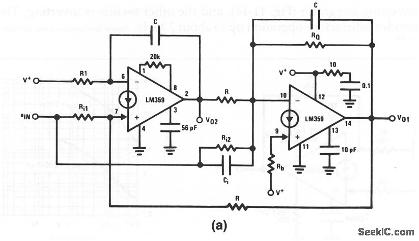
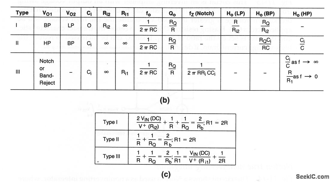
This circuit shows both sections of a dual Norton used to form a bi-quad filter. Figures 11-15B and 11-15C show the design equations and bias equations, respectively. Note that the basic circuit can be connected to provide three types of filter action. With type I, VO1 is a band-pass, and VO2 is a low-pass. With type II, VO1 is high-pass and VO2 is band-pass. With type II, VO1 is notch or band-reject, and VO2 is not used. Note that one section of the Norton is connected as a noninverting integrator (Fig. 11-14), and the other section is inverting. The circuit provides satisfactory operation up to about 2 MHz.
Reprinted Url Of This Article:
http://www.seekic.com/circuit_diagram/Amplifier_Circuit/Norton_bi_quad_filter.html
Print this Page | Comments | Reading(3)

Article Categories
power supply circuit
Amplifier Circuit
Basic Circuit
LED and Light Circuit
Sensor Circuit
Signal Processing
Electrical Equipment Circuit
Control Circuit
Remote Control Circuit
A/D-D/A Converter Circuit
Audio Circuit
Measuring and Test Circuit
Communication Circuit
Computer-Related Circuit
555 Circuit
Automotive Circuit
Repairing Circuit
Code: