Automotive Circuit
The motor burglarproof alarm (3)
Published:2011/7/23 20:30:00 Author:qqtang | Keyword: burglarproof alarm | From:SeekIC

The working principle of the circuit
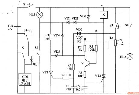
The motor alarm circuit consists of the diodes VD1-VD7, transistor V, thyristors VT1 and VT2, resistor R1-R6, capacitors C1 and C2, relay K, see as figure 7-72.
S1(S1-1, S1-2) is the motor lock switch, S2 is the neutral switch, S3 is the electric loudspeaker key, S4 is the brake switch. HL1 is the neutral gear indicator, HL2 is the brake lamp. GB is the motor battery.
Reprinted Url Of This Article:
http://www.seekic.com/circuit_diagram/Automotive_Circuit/The_motor_burglarproof_alarm_3.html
Print this Page | Comments | Reading(3)

Article Categories
power supply circuit
Amplifier Circuit
Basic Circuit
LED and Light Circuit
Sensor Circuit
Signal Processing
Electrical Equipment Circuit
Control Circuit
Remote Control Circuit
A/D-D/A Converter Circuit
Audio Circuit
Measuring and Test Circuit
Communication Circuit
Computer-Related Circuit
555 Circuit
Automotive Circuit
Repairing Circuit
Code: