
Index 7
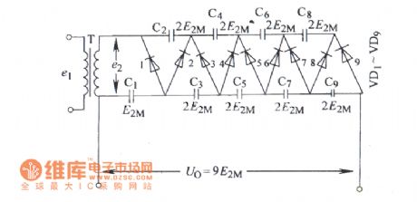
Ten times rectifier circuit diagram
Published:2014/2/16 21:30:00 Author: | Keyword: Ten times rectifier circuit diagram,

View full Circuit Diagram | Comments | Reading(787)
Nine times pressure rectifier circuit diagram
Published:2014/2/16 21:29:00 Author: | Keyword: Nine times pressure rectifier circuit diagram,
View full Circuit Diagram | Comments | Reading(704)
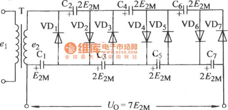
Seven times the pressure rectifier circuit (2) circuit diagram
Published:2014/2/16 21:29:00 Author: | Keyword: Seven times the pressure rectifier circuit (2) circuit diagram,
View full Circuit Diagram | Comments | Reading(740)
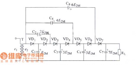
Seven times the pressure rectifier circuit (a) circuit diagram
Published:2014/2/16 21:28:00 Author: | Keyword: Seven times the pressure rectifier circuit (a) circuit diagram,
View full Circuit Diagram | Comments | Reading(640)
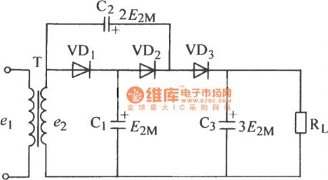
Three times the pressure rectifier circuit diagram
Published:2014/2/16 21:26:00 Author: | Keyword: Three times the pressure rectifier circuit diagram,
View full Circuit Diagram | Comments | Reading(739)
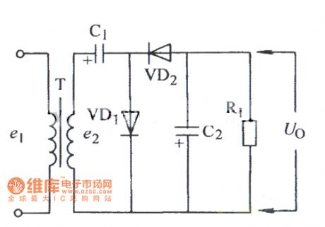
Double pressure rectifier circuit (2) circuit diagram
Published:2014/2/16 21:26:00 Author: | Keyword: Double pressure rectifier circuit (2) circuit diagram,
View full Circuit Diagram | Comments | Reading(724)
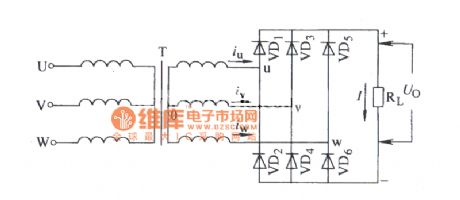
Three-phase bridge rectifier circuit diagram type resistance load
Published:2014/2/16 21:24:00 Author: | Keyword: Three-phase bridge rectifier circuit diagram type resistance load
View full Circuit Diagram | Comments | Reading(816)
CD-ROM interface circuit
Published:2014/2/16 20:48:00 Author:lynne | Keyword: CD-ROM interface circuit,
CD-ROM interface circuit shown in Fig.:
(View)
View full Circuit Diagram | Comments | Reading(1160)
Overspeed alarm indicator with hysteresis circuit diagram
Published:2014/2/16 20:51:00 Author:lynne | Keyword: Overspeed alarm indicator with hysteresis circuit diagram,
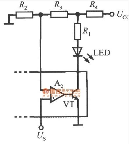
Overspeed alarm indicator with hysteresis circuit diagramshown in Fig.:
(View)
View full Circuit Diagram | Comments | Reading(856)
Overspeed alarm indicator circuit
Published:2014/2/16 20:53:00 Author:lynne | Keyword: Overspeed alarm indicator circuit,
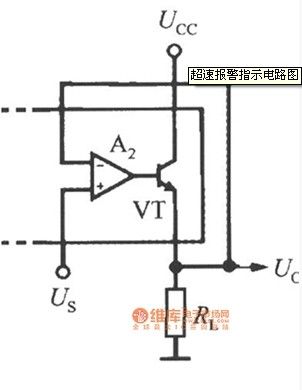
Overspeed alarm indicator circuit shown in Figure:
(View)
View full Circuit Diagram | Comments | Reading(632)
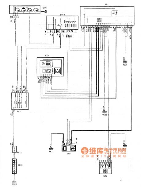
Dongfeng Peugeot Citroen Picasso 2.0L car horn circuit
Published:2014/2/16 21:02:00 Author:lynne | Keyword: Dongfeng Peugeot Citroen Picasso 2.0L car horn circuit,
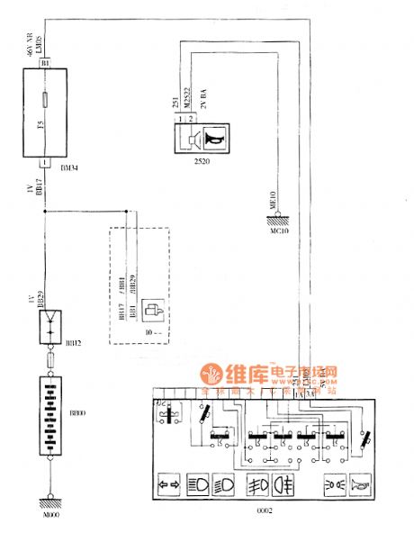
Dongfeng Peugeot Citroen Picasso 2.0L car horn circuit shown in Figure:
(View)
View full Circuit Diagram | Comments | Reading(752)
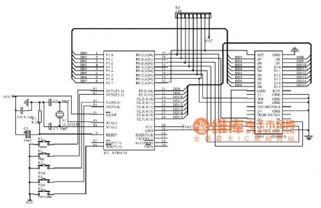
Single chip accelerometer MMA1220D and MCU interface circuit diagram
Published:2014/2/9 21:23:00 Author:lynne | Keyword: Single chip accelerometer MMA1220D and MCU interface circuit diagram,

Single chip accelerometer MMA1220D and MCU interface circuit diagram as shown:
(View)
View full Circuit Diagram | Comments | Reading(686)
Ground load circuit
Published:2014/2/9 21:33:00 Author:lynne | Keyword: Ground load circuit,
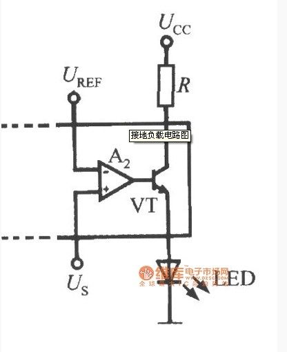
Ground load circuit shown in Figure:
(View)
View full Circuit Diagram | Comments | Reading(679)
Dragon 2.0L car cigarette lighter plug attachment circuit
Published:2014/2/7 20:06:00 Author:lynne | Keyword: Dragon 2.0L car cigarette lighter plug attachment circuit,

Dragon 2.0L car cigarette lighter plug attachment circuit shown in Figure:
(View)
View full Circuit Diagram | Comments | Reading(651)
Practical pressure regulating system circuit diagram
Published:2014/2/6 21:42:00 Author:lynne | Keyword: Practical pressure regulating system circuit diagram,

Practical pressure regulating system circuit diagram shown in Fig.:
A practical circuit pressure regulating system is shown in Fig . +12 V power supply through 78L05 (IC2) to get +5 V voltage , a separate power supply to the MPX5100 . The remaining circuits are used +12 V power supply. MC33033 (IC1) for the motor controller , MC34272 (IC3) is a dual op amp ( currently only one op amp ) . To improve efficiency, the motor drive circuit uses a MPM3002 -drive module internally by two P -channel power FET (V1, V2) and two N -channel power MOSFETs (V3, V4) bridge consisting of H , drive current up to 4A. Can drive DC brush motors. To avoid system noise or small pressure fluctuations caused by measurement error , but also specifically to increase the hysteresis circuit using MC33033 internal error amplifier and an external resistor R8 ~ R10, there is a lag effect constitutes a comparator . Its working principle is to open the motor when Uo <UREF time ; With the rising pressure of the pool , when the sensor output voltage is equal to the reference voltage hysteresis voltage (UH) the sum , ie Uo = UREF + UH when the motor is turned off , the system pressure reduction . Thereafter , the sensor output voltage will always be equal to the reference voltage drop when the motor turned up . Take R8 = R9 = 10kΩ, R10 = 300kΩ , the hysteresis voltage of 0.3V, corresponding to 7.5kPa lag pressure. Circuit switch S can be used to control the motor forward or reverse . (View)
View full Circuit Diagram | Comments | Reading(1023)
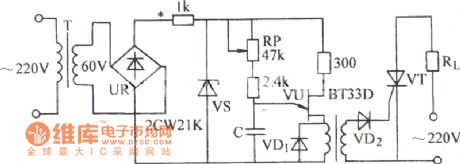
Common anode voltage thyristor trigger borrow circuit
Published:2014/2/6 21:39:00 Author:lynne | Keyword: Common anode voltage thyristor trigger borrow circuit,
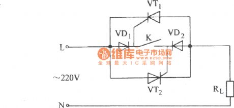
Common anode voltage thyristor trigger borrow circuit shown in Figure:
(View)
View full Circuit Diagram | Comments | Reading(737)
Electronic transformer with overcurrent protection circuit
Published:2014/2/6 21:44:00 Author:lynne | Keyword: Electronic transformer with overcurrent protection circuit,
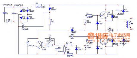
Electronic transformer with overcurrent protection circuit shown in Figure:
( 1 ) The core of the circuit is determined by C2, C3, T3, L3 trigger circuit with R2, double-ended C4, D7, L2 consists of two half-bridge circuit of the self-excited switching converter , which is a two-way trigger diode DB1 , the trigger voltage of 30V; T-L1-3 in the small high frequency magnetic ring ( diameter 7mm × 29mm × 12mm), the primary wire with a diameter of 0.50mm wound specifications lap 48 , the inductance of 9.5mH, with the secondary 30 diameter of 0.23mm enameled wire sizes from 5 laps , insulation between primary and secondary sets with suitable nylon , can be achieved CE safety standards.(2) Q1, C4, C5, R3, R4, D8, R8 composition overcurrent protection circuit , when the output level short circuit or overload , the voltage on resistor R2 will surge through D3, R3, R7, C8 divider Credit after triggering the transistor Q1 is turned on , so that the trigger switch can not be turned on and play a protective role , C4 role in protection from the state holding circuit.(3) C1, L1 arm consisting of LC type filter , fat filter spike pulse switch circuit. L1 wire with a diameter of 0.37mm specifications on the EE-20 types of high-frequency magnetic core made of 200 laps around the system . High-frequency magnetic core to be reserved between a gap to prevent core saturation , L1 inductance should be around well after about 6.9mH.(4) F1 is a fast-acting fuse to 800mA , R1 is varistors , F2 is the thermal insurance, should be installed and switch T2, T3 radiator connected together. The above elements can input circuit overcurrent , overvoltage protective effects and transistor overheating.(5) D5, D6, D8, D9, C6, C7 are output from the transformer L3 to the discharge peak inverse voltage applied . (View)
View full Circuit Diagram | Comments | Reading(3935)
Singlet ordinary thyristor control circuit
Published:2014/2/6 21:35:00 Author:lynne | Keyword: Singlet ordinary thyristor control circuit,
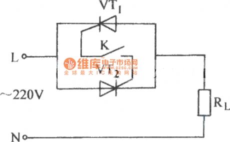
Singlet ordinary thyristor control circuit shown in Fig.:
(View)
View full Circuit Diagram | Comments | Reading(700)
Single-junction transistor synchronous triggering thyristors circuit
Published:2014/2/6 21:32:00 Author:lynne | Keyword: Single-junction transistor synchronous triggering thyristors circuit
Single-junction transistor synchronous triggering thyristors circuit shown in Figure:
(View)
View full Circuit Diagram | Comments | Reading(723)
Dongfeng Peugeot Citroen Picasso 2.0L car key not removed warning buzzer circuit diagram
Published:2014/1/24 20:35:00 Author:lynne | Keyword: Dongfeng Peugeot Citroen Picasso 2.0L car key not removed warning buzzer circuit diagram,
Dongfeng Peugeot Citroen Picasso 2.0L car keys are not removed warning buzzer circuit diagram shown in figure:
(View)
View full Circuit Diagram | Comments | Reading(977)
| Pages:7/471 1234567891011121314151617181920Under 20 |
Circuit Categories
power supply circuit
Amplifier Circuit
Basic Circuit
LED and Light Circuit
Sensor Circuit
Signal Processing
Electrical Equipment Circuit
Control Circuit
Remote Control Circuit
A/D-D/A Converter Circuit
Audio Circuit
Measuring and Test Circuit
Communication Circuit
Computer-Related Circuit
555 Circuit
Automotive Circuit
Repairing Circuit