
Index 439
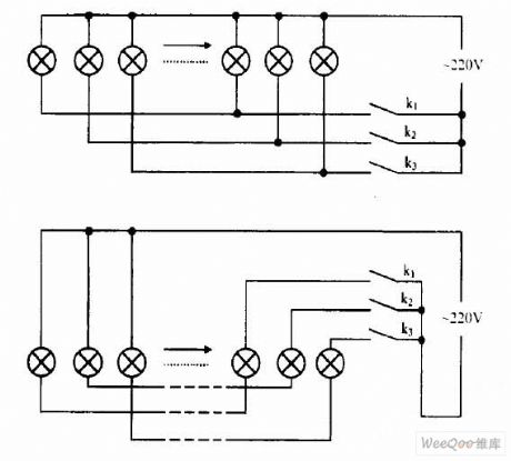
Colored Lights Join Methods Circuit
Published:2011/4/23 3:57:00 Author:Joyce | Keyword: ColoredLights, Join Methods,
View full Circuit Diagram | Comments | Reading(725)
LM567 Internal Structure Circuit
Published:2011/4/24 7:52:00 Author:Robert | Keyword: Internal Structure

LM567 Internal Structure Circuit is shown below:
(View)
View full Circuit Diagram | Comments | Reading(842)
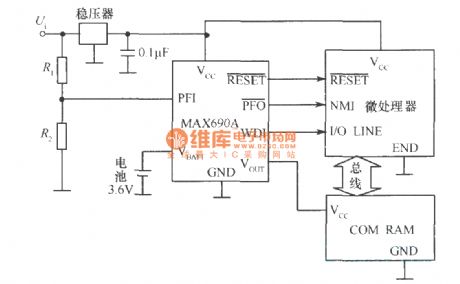
MAX690A/692A basic application circuit
Published:2011/4/22 4:47:00 Author:Nicole | Keyword: basic application
View full Circuit Diagram | Comments | Reading(1189)
MAX712/MAX713 pin arrangement mode
Published:2011/4/22 4:46:00 Author:Nicole | Keyword: pin arrangement
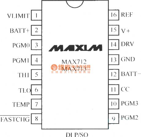
MAX712/MAX713 series are fast charging management chip produced by Maxim Company. MAX712/MAX713 chip is suitable for the charging of 1~16 bit Ni-MH battery or Ni-Cd battery. The pin arrangement diagram is shown as below:
(View)
View full Circuit Diagram | Comments | Reading(898)
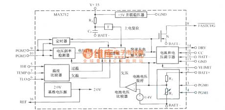
MAX712 internal structure block diagram
Published:2011/4/22 4:39:00 Author:Nicole | Keyword: internal structure
View full Circuit Diagram | Comments | Reading(789)
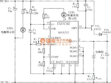
MAX712 application circuit(charging circuit)
Published:2011/4/22 4:38:00 Author:Nicole | Keyword: charging
View full Circuit Diagram | Comments | Reading(2088)
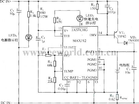
MAX712 application circuit charging circuit
Published:2011/4/22 4:37:00 Author:Nicole | Keyword: charging
View full Circuit Diagram | Comments | Reading(1593)
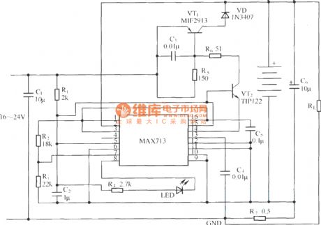
MAX713 application circuit under linear model
Published:2011/4/22 4:36:00 Author:Nicole | Keyword: linear model
View full Circuit Diagram | Comments | Reading(2561)
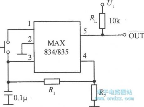
MAX834/835 typical application circuit
Published:2011/4/22 4:33:00 Author:Nicole | Keyword: typical application
View full Circuit Diagram | Comments | Reading(524)
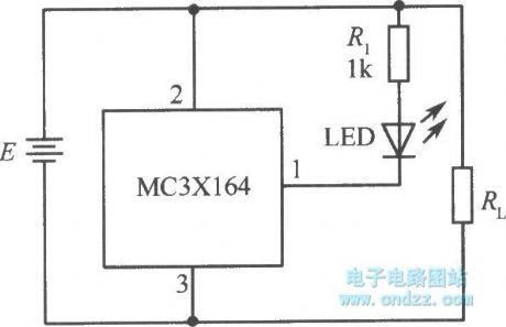
Reset circuit composed of MC3X164 series
Published:2011/4/22 4:18:00 Author:Nicole | Keyword: reset
View full Circuit Diagram | Comments | Reading(470)
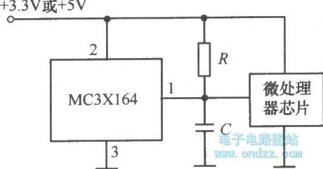
MC3X164 series typical application circuit
Published:2011/4/22 4:10:00 Author:Nicole | Keyword: typical application
View full Circuit Diagram | Comments | Reading(537)
Internal structure of UC3906
Published:2011/4/22 3:54:00 Author:Nicole | Keyword: internal structure
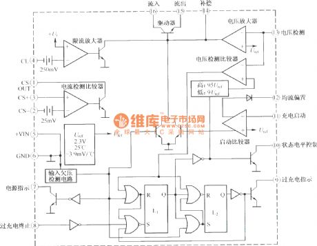
As VRLA battery charge special chip, UC3906 has 3 kinds of charging logic control and detection function to achieve the best charge of VRLA battery, it also has the functions of environmental temperature self-adapting, charge-discharge extent self-adapting, and current limiting, under-voltage protection. The adopted temperature compensation technology can make all kinds of charging transformational voltage change in relation to the VRLA battery voltage temperature coefficient, then the VRLA battery will reach the best charging state within a wide temperature range. The internal structure diagram is shown as below:
(View)
View full Circuit Diagram | Comments | Reading(1499)
Infrared automatic faucet circuit diagram
Published:2011/4/21 8:44:00 Author:Rebekka | Keyword: Infrared automatic faucet
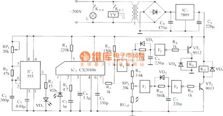
The circuit is composed of the parts below:
(1) infrared emitterThe multi-harmonic oscillator is comoposed of 555 circuit.The oscillation frequency is decided by value of the RP1, R1, C1. The circuit's oscillation frequency is 38kHz.
(2) infrared receiver circuitThe circuit is composed of infrared receiver tube VD2 and CX20106.
(3) water valve control circuitThe circuit is composed of controlled gate F1, F2 and drive tube VT1 and relay K1.
(4) lamp control circuitThe circuit is composed of the control gate F3, F4, drive tube VT2 and relay K2. (View)
View full Circuit Diagram | Comments | Reading(2520)
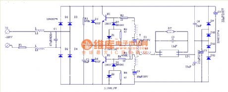
Common inverter principle diagram on the market(12VDC to 220VAC 150W)
Published:2011/4/22 1:55:00 Author:Nicole | Keyword: inverter
View full Circuit Diagram | Comments | Reading(2522)
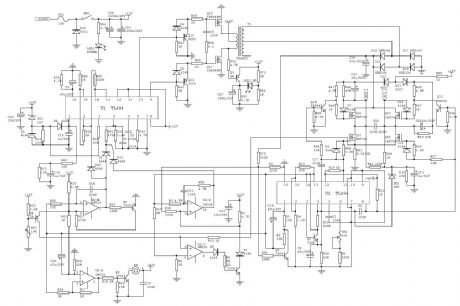
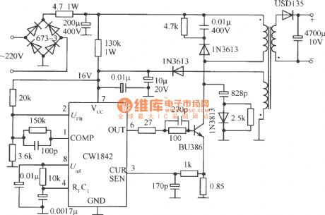
Single end fly back converter circuit external connected ambipolar power tube by CWI842
Published:2011/4/20 22:29:00 Author:May | Keyword: Single end, fly back, converter, ambipolar power tube
View full Circuit Diagram | Comments | Reading(570)
40W fluorescent light electron ballast electrical schematic diagram
Published:2011/4/21 4:07:00 Author:May | Keyword: 40W, fluorescent light, electron ballast
View full Circuit Diagram | Comments | Reading(2682)
EW-8W electron ballast
Published:2011/4/21 4:04:00 Author:May | Keyword: electron ballast

View full Circuit Diagram | Comments | Reading(620)
IR21571 straight tube type integrated circuit electron ballast
Published:2011/4/21 3:52:00 Author:May | Keyword: straight tube type, integrated circuit, electron ballast

IR21571 is designed for straight tube type ballast in specialty. It sums up various kinds functions of IR2156 and add new protection function of miss match and under voltage. (View)
View full Circuit Diagram | Comments | Reading(725)
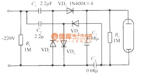
Voltage multiplying rectifier electron ballast circuit
Published:2011/4/21 3:46:00 Author:May | Keyword: Voltage multiplying rectifier, electron ballast
View full Circuit Diagram | Comments | Reading(1033)
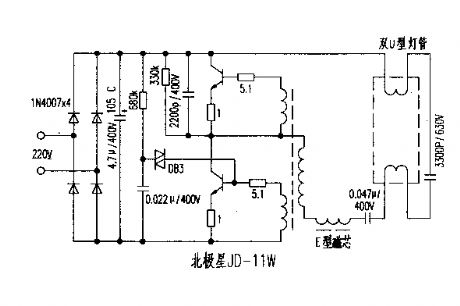
North Star JD-11W electron ballast circuit
Published:2011/4/21 3:43:00 Author:May | Keyword: North Star, electron ballast
View full Circuit Diagram | Comments | Reading(743)
| Pages:439/471 At 20421422423424425426427428429430431432433434435436437438439440Under 20 |
Circuit Categories
power supply circuit
Amplifier Circuit
Basic Circuit
LED and Light Circuit
Sensor Circuit
Signal Processing
Electrical Equipment Circuit
Control Circuit
Remote Control Circuit
A/D-D/A Converter Circuit
Audio Circuit
Measuring and Test Circuit
Communication Circuit
Computer-Related Circuit
555 Circuit
Automotive Circuit
Repairing Circuit