Digital Circuit
70_dB_VOLTAGECONTROLLED_GAIN
Published:2009/6/25 22:24:00 Author:May | From:SeekIC
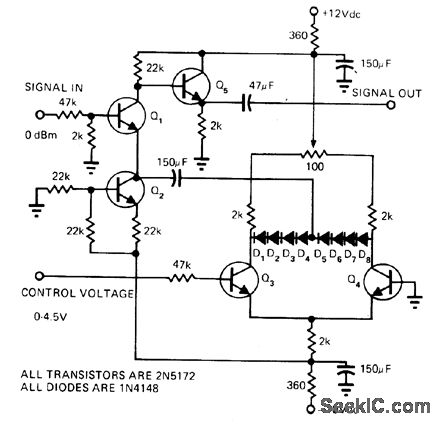
Amplifier Q1 uses current source Q2 as emitter resistor to provide correct current bias for class A operation. Coupling through 150-μF capacitor to silicon diode string D1-D8 provides variable re-sistance needed to achieve variable gain. Sim-ple differential amplifier Q3-Q4 adjusts forward bias of diodes to change their forward resis-tanco. Increasing positive control voltage from 0 to 4.5 V changes voltage gain from -74 dBm to about -4 dBm with respect to 0-dBm input signaL-N.A Steiner, Voltage-Controlled Am-plifier Covers 70 dB Range, EDN Magazine, March 5, 1975, p 72 and 74.
Reprinted Url Of This Article:
http://www.seekic.com/circuit_diagram/Basic_Circuit/Digital_Circuit/70_dB_VOLTAGECONTROLLED_GAIN.html
Print this Page | Comments | Reading(3)

Article Categories
power supply circuit
Amplifier Circuit
Basic Circuit
LED and Light Circuit
Sensor Circuit
Signal Processing
Electrical Equipment Circuit
Control Circuit
Remote Control Circuit
A/D-D/A Converter Circuit
Audio Circuit
Measuring and Test Circuit
Communication Circuit
Computer-Related Circuit
555 Circuit
Automotive Circuit
Repairing Circuit
Code: