Basic Circuit
Drift zeroing circuit of logarithmic and logarithmic ratio amplifier LOG101/104
Published:2012/8/22 21:02:00 Author:Ecco | Keyword: Drift zeroing , logarithmic , logarithmic ratio , amplifier | From:SeekIC
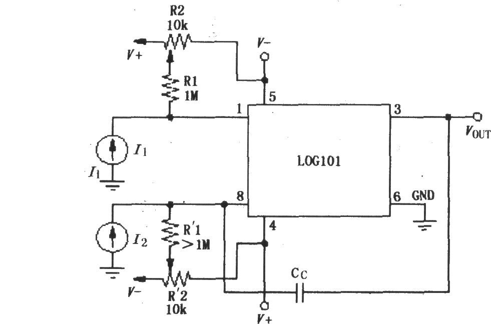
LOG101/104 input current I1/I2 is limited in the range of 100pA ~ 3.5mA, and if input current is greater than 3.5mA, the nonlinearly will be increased; if input current is less than 100pA, the input bias current ( typical value 5pA) will cause the input error to increase. When ± 5V supply operates, the input current (I1 + I2) is limited to 4.5mA. The circuit uses two 10kΩ potentiometers R2, R'2 to zero the input bias current of internal amplifiers A1 , A2. The internal amplifiers A1 , A2 control the field - effect transistor (FET) input, so the FET input has bias current characteristics, and temperature increases to 10 ℃ will double the input bias current.
Reprinted Url Of This Article:
http://www.seekic.com/circuit_diagram/Basic_Circuit/Drift_zeroing_circuit_of_logarithmic_and_logarithmic_ratio_amplifier_LOG101_104.html
Print this Page | Comments | Reading(3)

Article Categories
power supply circuit
Amplifier Circuit
Basic Circuit
LED and Light Circuit
Sensor Circuit
Signal Processing
Electrical Equipment Circuit
Control Circuit
Remote Control Circuit
A/D-D/A Converter Circuit
Audio Circuit
Measuring and Test Circuit
Communication Circuit
Computer-Related Circuit
555 Circuit
Automotive Circuit
Repairing Circuit
Code: