Filter Circuit
CAPACITORLESS_NOTCH_FILTER
Published:2009/7/13 10:29:00 Author:May | From:SeekIC
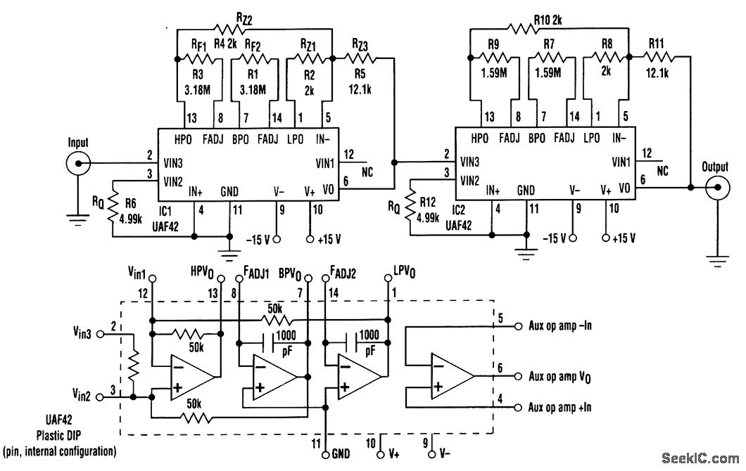
The notch frequency for the filter is set by fnotch+[(ALP/AHP)×(RZ2/RZ1)]×f0where ALP and AHP are the gain from input to low-pass output at f=0 Hz,and the gain from input to high-pass output at f≤f0,respectively. Typically ((ALP/AHP)×(RZ2/RZ1)=1;therefore,fnotch=f0,and is gtven by f0=1/(2π)(RFC)where RF=RF1=RF2, and C=C1=C2. The -3-dB bandwidth is determined by the following relation∶BW-3dB=fnotch/Q, where BW-3dB=fH-fL. The Q of the filter affects the passband gainc(which should be adjusted to unity) and is related to the ratio of the resistances RZ3 to RZ1 and RZ3 to RZ2. In other words,Q=(RZ3/RZ1)=(RZ3/RZ2). Q also is related to RQ by the follOwing relation∶RQ=(25 kΩ/Q-1).
Reprinted Url Of This Article:
http://www.seekic.com/circuit_diagram/Basic_Circuit/Filter_Circuit/CAPACITORLESS_NOTCH_FILTER.html
Print this Page | Comments | Reading(3)

Article Categories
power supply circuit
Amplifier Circuit
Basic Circuit
LED and Light Circuit
Sensor Circuit
Signal Processing
Electrical Equipment Circuit
Control Circuit
Remote Control Circuit
A/D-D/A Converter Circuit
Audio Circuit
Measuring and Test Circuit
Communication Circuit
Computer-Related Circuit
555 Circuit
Automotive Circuit
Repairing Circuit
Code: