Filter Circuit
FOUR_CRYSTAL_FILTER
Published:2009/7/3 4:10:00 Author:May | From:SeekIC
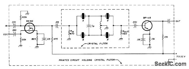
Uses two matched sets of crystals, with each pair having maximum frequency difference of 25 Hz.Transistors serve as input and output isolating stages. Each matched pair, such as A-A', should be from same manufacturer and have same nominal parallel capacitance for circuit, same activity, and same resonant frequency within 25 Hz. Artide gives detailed instructions for grinding crystal to increase resonant frequency when necessary for matching. Use frequency counter for checking frequency. Values given in circuit are for 5.645-MHz crystal filter with -6dB band-pass of L82 kHz and insertion loss of about 5 dB. Crystals used are 5.644410 MHz and 5.644416 MHz for A and A', and 5.645627 MHz and 5.645641 MHz for B and B'. Coil has 7 + 7 turns No.28 enamel bifilar wound on 10.7-MHz IF transformer having 2.4-mm slug diameter. C, is 39 to 47 pF.-J. Perolo, Practical Considera-tions in Crystal-Filter Design, Ham Radio. Nov.1976, p 34-38.
Reprinted Url Of This Article:
http://www.seekic.com/circuit_diagram/Basic_Circuit/Filter_Circuit/FOUR_CRYSTAL_FILTER.html
Print this Page | Comments | Reading(3)

Article Categories
power supply circuit
Amplifier Circuit
Basic Circuit
LED and Light Circuit
Sensor Circuit
Signal Processing
Electrical Equipment Circuit
Control Circuit
Remote Control Circuit
A/D-D/A Converter Circuit
Audio Circuit
Measuring and Test Circuit
Communication Circuit
Computer-Related Circuit
555 Circuit
Automotive Circuit
Repairing Circuit
Code: