Filter Circuit
PROGRAMMER_FOR_SIGNETICS_8223
Published:2009/7/3 4:10:00 Author:May | From:SeekIC
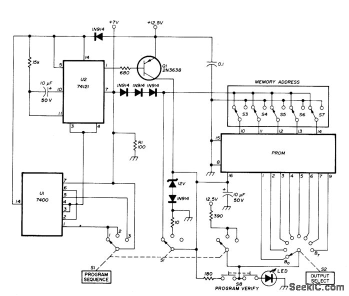


Bounceless switch U1 triggers mono MVBR U2, both operating at 7 V above ground. When Q1is saturated by pulse from U2, it applies 250-ms 12.5-V programming pulse to VCC terminal (pin 16) of memory chip and opens fuse at previously addressed bit to make it logic 1. Separate regulators are required for 7 V and 12.5 V. Used with alphameric display having five 7-segment digits in circuit serving as function/units indicator for interval timericounter, where it forms simulation of abbreviations for time and frequency units. Articlegives step-by-step instructions for mistake-free operation of programmer.-J. W. Springer, Function/Units Indicator Using LED Displays, Ham Radio, March 1977, p 58-63.
Reprinted Url Of This Article:
http://www.seekic.com/circuit_diagram/Basic_Circuit/Filter_Circuit/PROGRAMMER_FOR_SIGNETICS_8223.html
Print this Page | Comments | Reading(3)

Article Categories
power supply circuit
Amplifier Circuit
Basic Circuit
LED and Light Circuit
Sensor Circuit
Signal Processing
Electrical Equipment Circuit
Control Circuit
Remote Control Circuit
A/D-D/A Converter Circuit
Audio Circuit
Measuring and Test Circuit
Communication Circuit
Computer-Related Circuit
555 Circuit
Automotive Circuit
Repairing Circuit
Code: