Filter Circuit
STATE_VARIABLE_ACTIVE_FILTER
Published:2009/7/6 8:22:00 Author:May | From:SeekIC
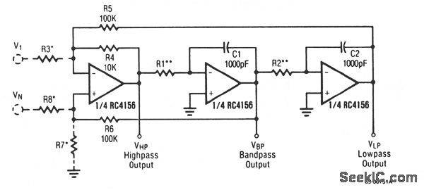
A generalized circuit diagram of the two-pole state-variable active filter is shown. The state-variable filter can be inverting or noninverting and can simultaneously provide three outputs: low-pass, bandpass, and high-pass. A notch filter can be realized by adding one summing op amp.
In the state-variable filter circuit, one amplifier performs a summing function and the other two act as integrators. The choice of passive component values is arbitrary, but must be consistent with the amplifier operating range and input signal characteristics. The values shown for C1, C2, R4, R5, and R6 are arbitrary. Preselecting their values will simplify the filter tuning procedures, but other values can be used if necessary.
Reprinted Url Of This Article:
http://www.seekic.com/circuit_diagram/Basic_Circuit/Filter_Circuit/STATE_VARIABLE_ACTIVE_FILTER.html
Print this Page | Comments | Reading(3)

Article Categories
power supply circuit
Amplifier Circuit
Basic Circuit
LED and Light Circuit
Sensor Circuit
Signal Processing
Electrical Equipment Circuit
Control Circuit
Remote Control Circuit
A/D-D/A Converter Circuit
Audio Circuit
Measuring and Test Circuit
Communication Circuit
Computer-Related Circuit
555 Circuit
Automotive Circuit
Repairing Circuit
Code: